
Control device

a control device and mouse technology, applied in the direction of instruments, cathode-ray tube indicators, computing, etc., can solve the problems of inability to meet the ergonomic demands of users, improper gestures of holding the mouse, and inadvertent force on the user's hand, so as to achieve a high level of sensing accuracy and minimize the vertical height of the control device

Inactive Publication Date: 2012-06-28
HSU JUNG CHANG
View PDF12 Cites 6 Cited by
  • Summary
  • Abstract
  • Description
  • Claims
  • Application Information

AI Technical Summary

Benefits of technology

[0009]The present invention further provides a control device, in which a sliding-auxiliary element is located at an end of a roller for reducing the friction of the roller during the roller is rotated or moved. Under this circumstance, a small force is sufficient to allow the user's fingers to be moved back and force to easily operate the roller while increasing the operating smoothness.
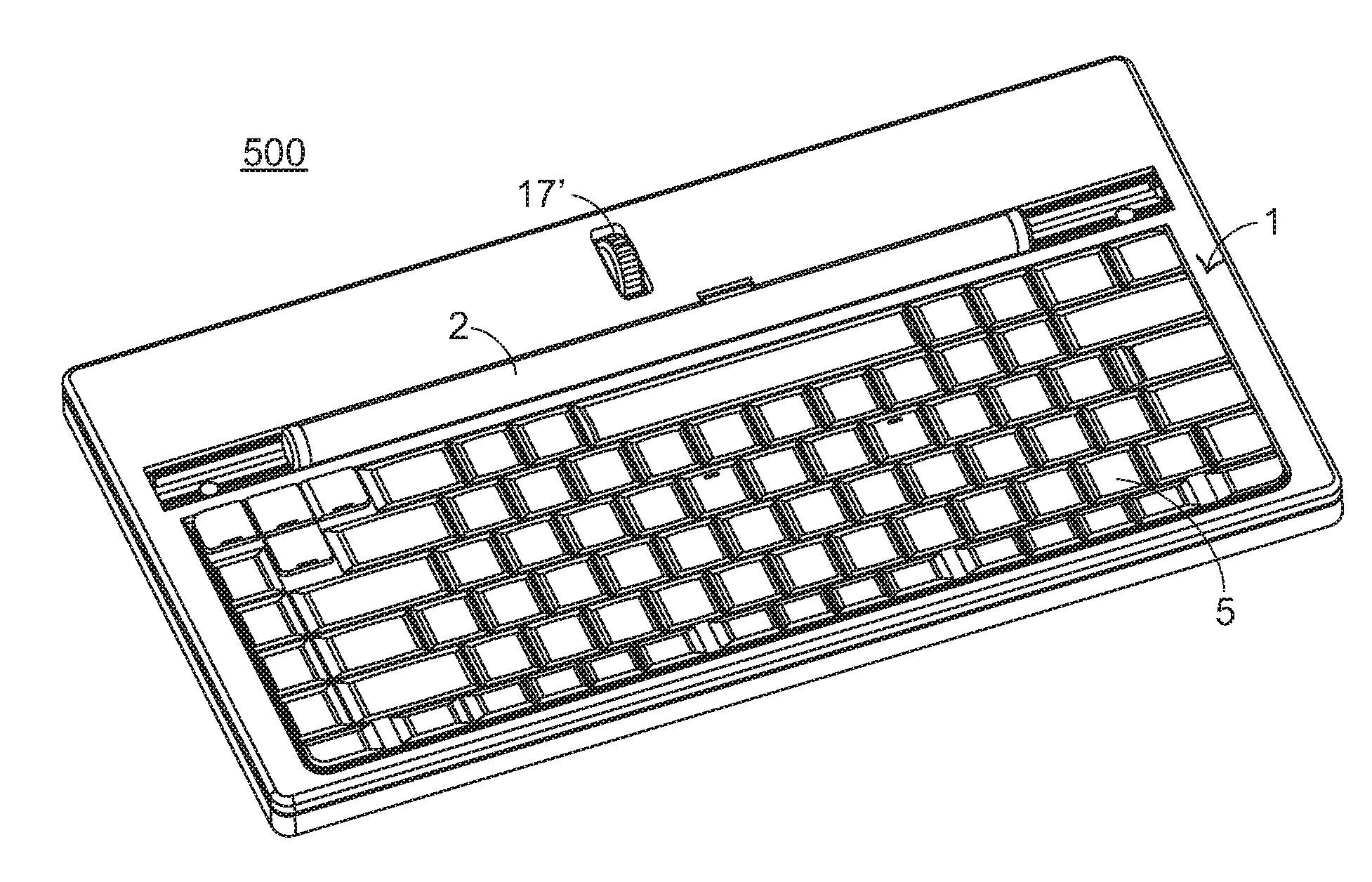
[0011]The present invention further provides a control device with a variety of peripheral devices, so that the applications of the control device are more versatile. For example, the control device may integrate a scanner, a keyboard, a vertical-type machine, or the like.
[0035]Further, the sensor module of the circuit module is mounted on the outside of the carrier frame at one lateral side corresponding to the opening of the carrier frame for detecting the direction and amount of movement of the rolling roll. It simply needs to provide a space below the carrier frame for allowing vertical movement of the carrier frame and for accommodating the balance bar. Therefore, the vertical height of the control device can be minimized and, outside dust will not enter the opening to cover the sensor module, assuring a high level of sensing accuracy.
[0036]Further, the carrier frame can be prepared from POM, PTFE or any other self-lubricating material to reduce friction. Further, supplementary elements may be used to facilitate rotation of the rolling roll in the rotation groove.
[0037]Further, the rolling roll can be a solid roll. Alternatively, the rolling roll can be a tubular roll having an axial through hole extending through the two distal ends thereof for accommodating weights to adjust the total weight of the rolling roll. Further, a magnetically permeable core member may be fitted into the axial through hole of the rolling roll. Further, magnetic members may be affixed to the carrier frame to attract the magnetically permeable core member in the axial through hole of the rolling roll, securing the rolling roll to the carrier frame and avoiding falling of the rolling roll out of the carrier frame accidentally due to an excessive amount of applied force during operation of the control device.

Problems solved by technology

However, most of the commercially available mouse devices are not based on the ergonomic demands.
Consequently, during operation of the non-ergonomic mouse, the improper gesture of holding the mouse may apply inadvertent force by the user's hand.
A long time period of continuously operating the conventional mouse may cause pain in the user's hand.
If the user ignores the hand's pain at the initial stage and continuously uses the poorly-designed mouse, the user's hand may be suffered from permanent work injury.
After the mouse has been used for a long period and frequently used, the hand of the user is readily suffered from a carpal tunnel syndrome.
Since the mouse may be raised and the location is largely changed according to the use habits of many users, the usefulness of the wrist pad is largely reduced.

Method used


Image

  • Control device
  • Control device
  • Control device

Examples


Embodiment Construction

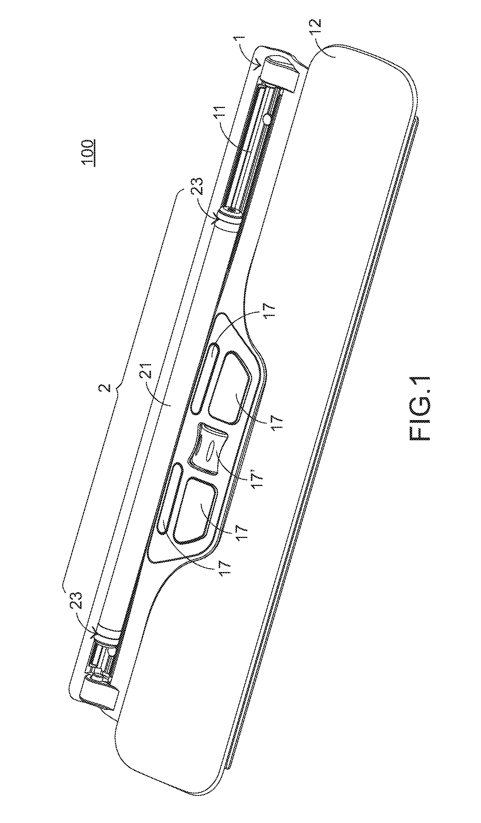
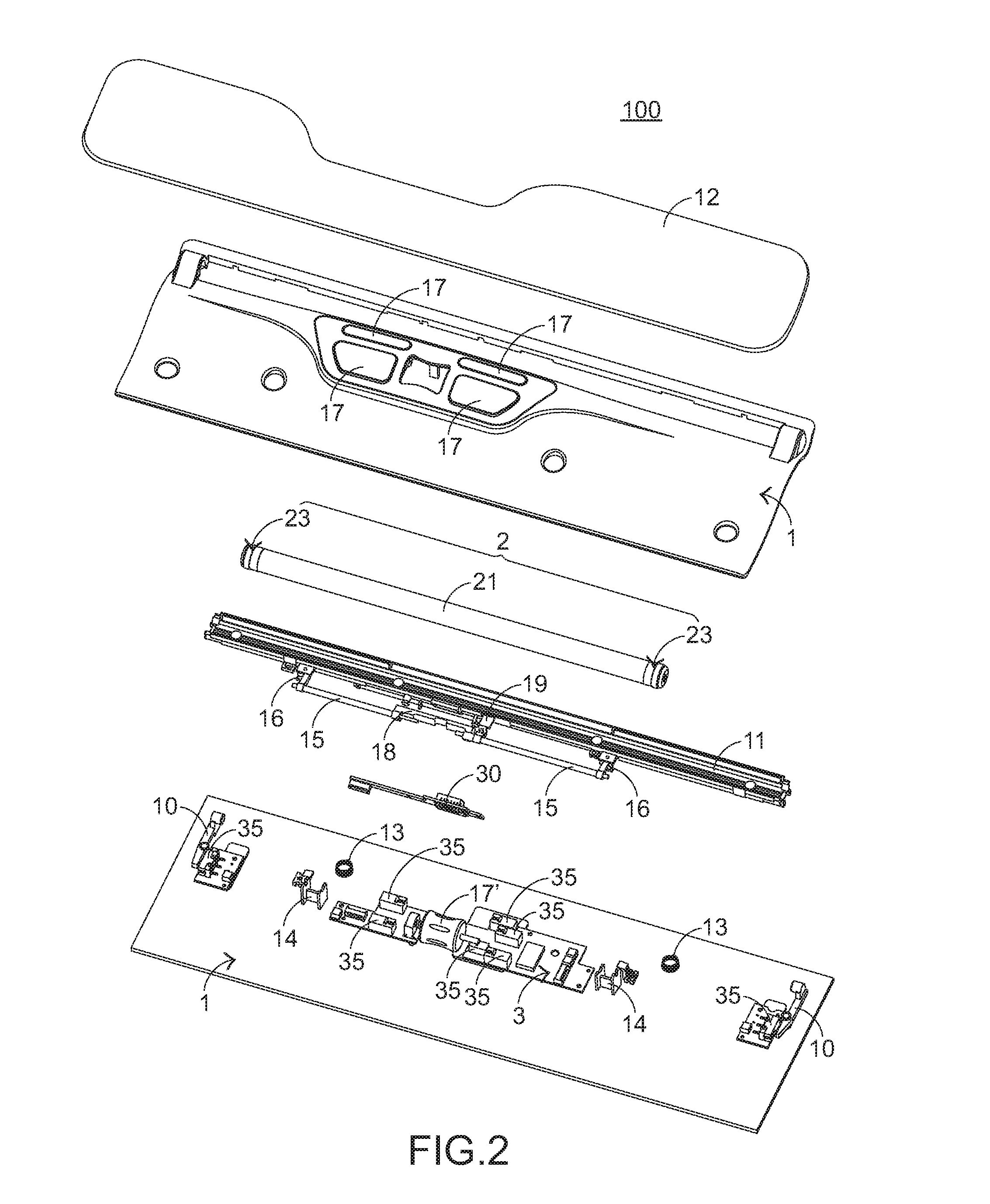
[0054]Please refer to FIGS. 1, 2 and 3. FIG. 1 is a schematic perspective view illustrating a control device according to a first embodiment of the present invention. FIG. 2 is a schematic exploded view illustrating the control device as shown in FIG. 1. FIG. 3 is a schematic perspective view illustrating the inner components of the control device as shown in FIG. 1.

[0055]As shown in FIG. 1, the control device 100 comprises a main body 1 and a roller 2 (or named rolling roll). The main body 1 comprises a holder 11, or named carrier frame. The holder 11 with a rotation groove is exposed outside. The roller 2 is disposed on the rotation groove of the holder 11. Consequently, the roller 2 may be removed from the holder 11 by a user; the roller 2 may be placed on the holder 11 by the user; or the roller 2 may be operated by the user to be moved leftwards / rightwards or rotated forwardly / backwardly on the holder 11. Since the user's hand is usually in contact with various articles, the us...


PUM


Abstract

A control device for controlling a cursor is provided. The control device includes a main body, a roller, and a circuit board. The main body has a holder. The roller is detachably disposed on the holder. The circuit module includes a detecting module for detecting movement and rotation of the roller on the holder. The roller includes a roller body and an assembled sliding mechanism. The assembled sliding mechanism is connected with the roller body and contacted with the holder. Consequently, during the roller is operated by a user, the friction generated by the roller is minimized.

Description

CROSS-REFERENCE TO RELATED APPLICATION[0001]This application is a continuation-in-part application of U.S. patent application Ser. No. 12 / 656,955, field Feb. 22, 2010 and hereby incorporates the content of this application by reference.FIELD OF THE INVENTION[0002]The present invention relates to a control device, and more particularly to a control device for controlling a cursor by using a detachable roller.BACKGROUND OF THE INVENTION[0003]With increasing development of science and technology, the computing performance of personal computers becomes more powerful. Consequently, personal computers are widely used to do various matters in our daily lives. For example, personal computers may be used at work to receive / transmit electronic mails and process documents. In addition, people may use personal computer to obtain information (e.g. information searching) and achieve leisure entertainment (e.g. music appreciation and games). Consequently, people spend much time in operating the pe...

Claims


Application Information

Patent Timeline
Patent Type & Authority Applications(United States)
IPC IPC(8): G06F3/033
CPCG06F3/0213H01H2019/146H01H25/008G06F3/0362
Inventor NIEN, CHUNG-YUEHCHENG, YU-CHIHCHIANG, HSIAO-LONG
Owner HSU JUNG CHANG
Learn More