System and method for dynamically determining a force applied through a rail vehicle axle

a technology of dynamic determination and axle, applied in the field of rail vehicles, can solve the problems of not being able to dynamically adjust, and generating more tractive effor

Inactive Publication Date: 2012-07-05
GENERAL ELECTRIC CO
View PDF7 Cites 4 Cited by
  • Summary
  • Abstract
  • Description
  • Claims
  • Application Information

AI Technical Summary

Problems solved by technology

Consequently, the heavier a locomotive, the more tractive effort that it can generate.
In conventional locomotive systems, the weight distribution among the powered axles and nonpowered axles is statically adjusted prior to shipment, and is not capable of being dynamically adjusted once the locomotive trip has begun.

Method used


Image

  • System and method for dynamically determining a force applied through a rail vehicle axle
  • System and method for dynamically determining a force applied through a rail vehicle axle
  • System and method for dynamically determining a force applied through a rail vehicle axle

Examples


Embodiment Construction

[0030]Reference will now be made in detail to the embodiments consistent with the invention, examples of which are illustrated in the accompanying drawings. Wherever possible, the same reference numerals are used throughout the drawings and refer to the same or like parts.

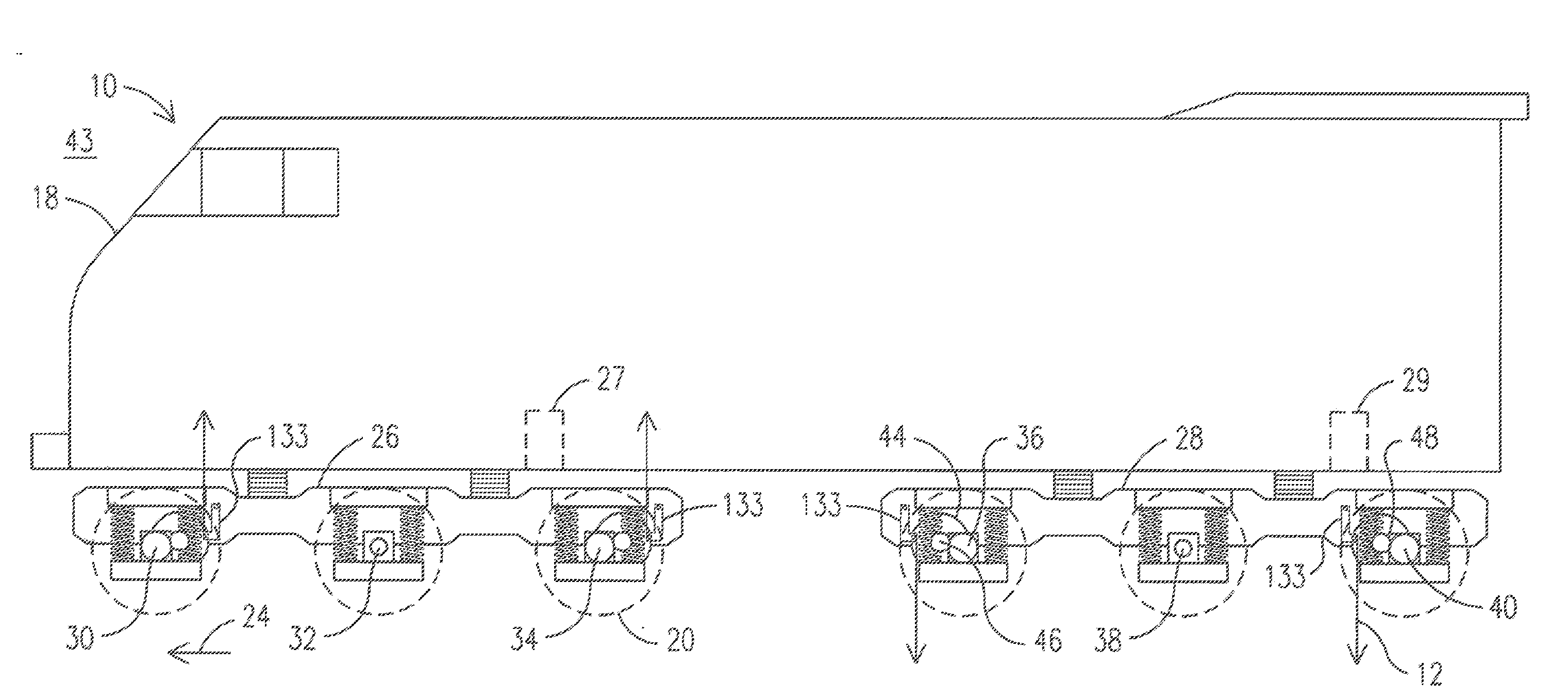
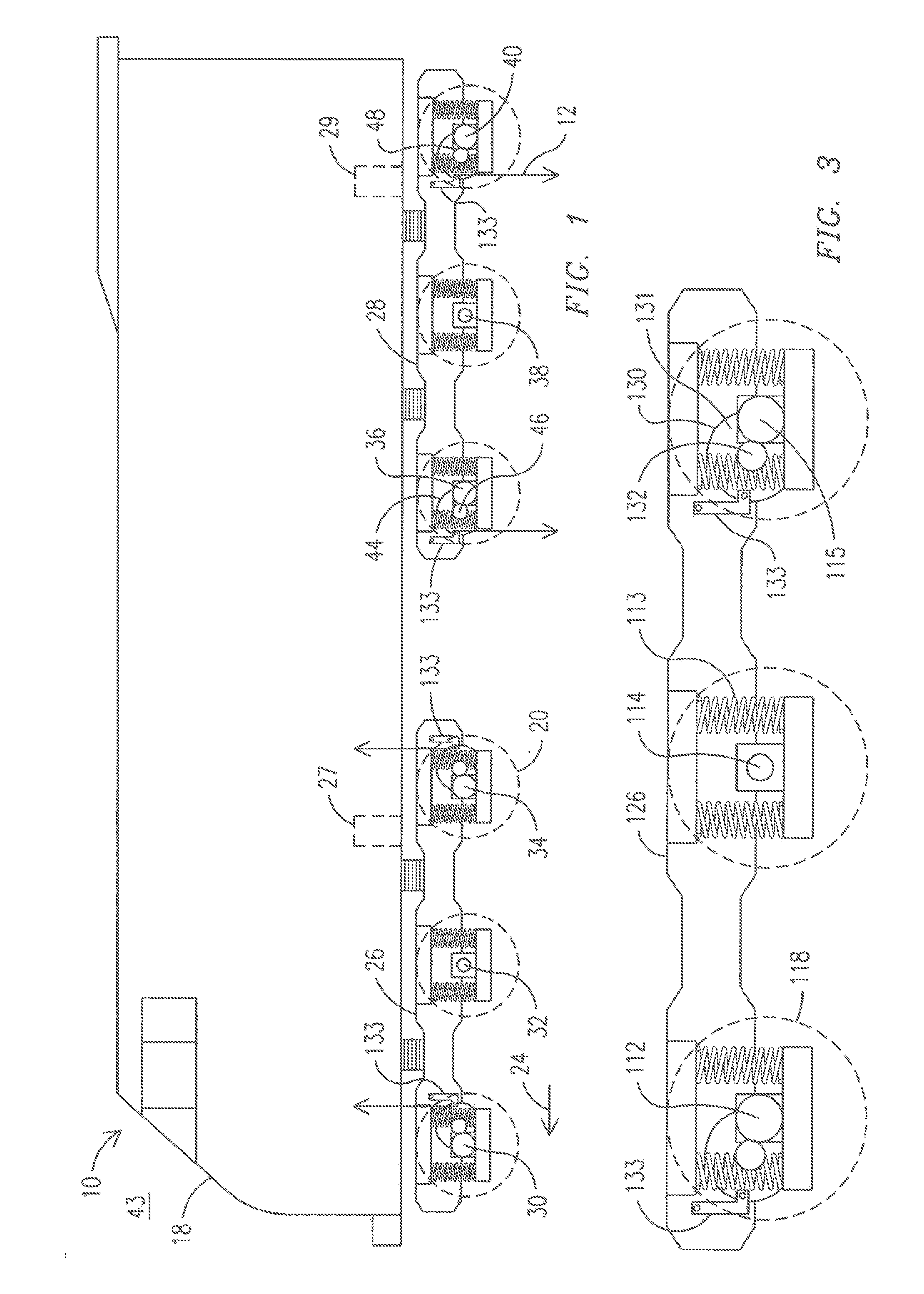
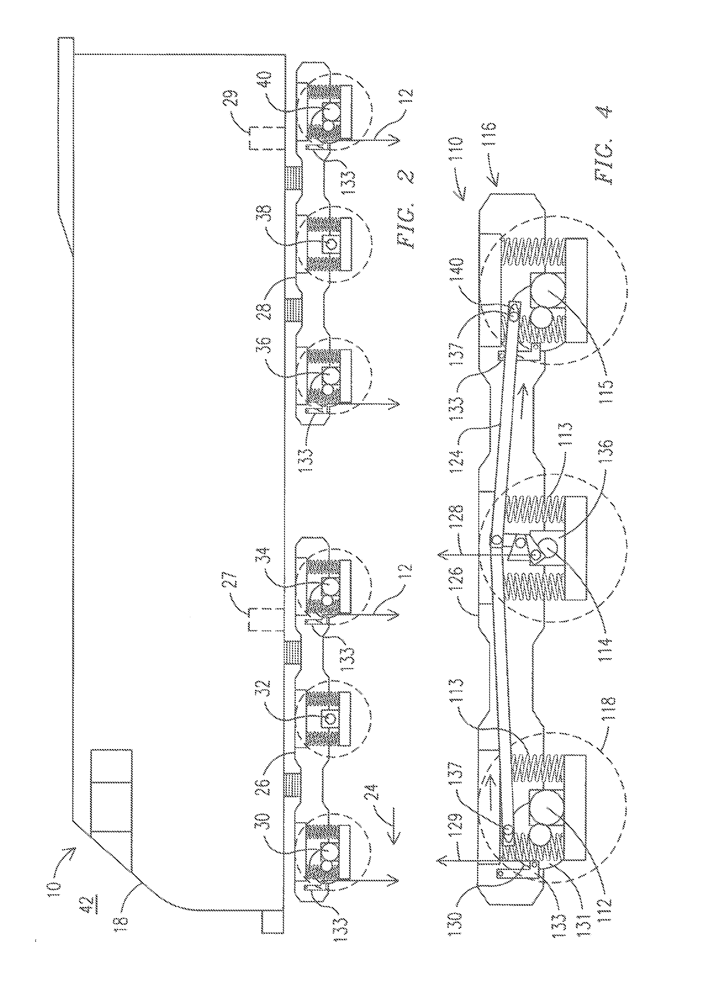
[0031]FIG. 1 illustrates an exemplary embodiment of a system 10 for dynamically affecting a normal force 12 applied through one or more of a plurality of locomotive axles 30,32,34,36,38,40. Although FIG. 1 illustrates a locomotive 18, the embodiment of the system 10 of the present invention, and all embodiments of the present invention discussed below, may be utilized with any rail vehicle, including a locomotive, for example. The locomotive 18 illustrated in FIG. 1 is configured to travel along a rail track (not shown), and includes a plurality of locomotive wheels 20 which are each received by a respective axle 30,32,34,36,38,40. The plurality of wheels 20 received by each axle 30,32,34,36,38,40 are configured to...


PUM


Abstract

A system is provided for dynamically determining a force applied through a plurality of axles in a rail vehicle configured to travel along a rail track in a travel direction. The rail vehicle includes a plurality of wheels received by the plurality of axles. The system includes a controller configured to determine a respective dynamic weight shift of the plurality of wheels on the rail track based upon a dynamic factor of the rail vehicle as the rail vehicle travels along the rail track.

Description

CROSS REFERENCE TO RELATED APPLICATIONS[0001]This application is a divisional of U.S. patent application Ser. No. 11 / 871,753 filed Oct. 12, 2007, the disclosure of which is incorporated by reference in its entirety for all purposes.BACKGROUND OF THE INVENTION[0002]The subject matter herein relates to rail vehicles, and, more particularly, to a system for dynamically determining a force applied through a plurality of locomotive axles in a locomotive.[0003]A diesel-electric locomotive typically includes a diesel internal combustion engine coupled to drive a rotor of at least one traction alternator to produce alternating current (AC) electrical power. The traction alternator may be electrically coupled to power one or more electric traction motors mechanically coupled to apply torque to one or more axles of the locomotive. The traction motors may include AC motors operable with AC power, or direct current motors operable with direct current (DC) power. For DC motor operation, a rectif...

Claims


Application Information

Patent Timeline
Patent Type & Authority Applications(United States)
IPC IPC(8): G05D1/02G06F19/00
CPCB61C15/04B61C15/08B61F3/04B60L2200/26G01G19/086B61C17/12G01G19/047
Inventor KUMAR, AJITH KUTTANNAIRWORDEN, BRET DWAYNE
Owner GENERAL ELECTRIC CO
Why Eureka
Try Eureka