Motorbike steering and suspension system

a suspension system and motorbike technology, applied in the direction of steering devices, axle suspensions, bicycle brakes, etc., can solve the problems of power consumption, affecting the balance and stability of the machine, and the front suspension tends to compress during the compression period, so as to improve feedback and control, the effect of more responsive steering and maintaining stability

Inactive Publication Date: 2014-12-11
WALTON ROBERT CHRISTOPHER
View PDF8 Cites 8 Cited by
  • Summary
  • Abstract
  • Description
  • Claims
  • Application Information

AI Technical Summary

Benefits of technology

[0009]This system has certain direct technical advantages: The use of a forward leaning rake allows a smaller trail to be used while maintaining neutral steering. In turn, a reduced trail produces simultaneously more responsive steering, while maintaining stability. For example, if the bike is stationary and upright, and the handlebars are turned fully to one side, they tend to straighten with the present invention, so directing the front wheel towards the direction of motion. This does not happen with a convention bike. With the present invention the steering and suspension mechanisms are separated. That is, different components are provided for suspension and steering functions, intended to improve feedback and control. Linear motion sliding joints, such as those in telescopic forks are avoided, and so therefore are the stick-friction effects associated with them. On a motorbike fitted with telescopic forks, there is a tendency for the front suspension to compress during braking (dive) due to weight shift. This lowers the front of the machine and alters the steering geometry, which unnecessarily uses up suspension travel, and alters the rake and trail, so altering the balance and stability of the machine as the brakes are applied. With the present invention, the braking system may be tuned to eliminate or reduce dive. This in turn allows softer suspension to be used, while keeping the machine more level during braking, and the steering geometry more constant.
[0010]There are other advantages that are indirectly possible with the use of this system. For example, at 100 miles per hour a vehicle needs about eight times more power than at 50 miles per hour to overcome aerodynamic drag. If the drag is reduced, not only can the vehicle increase its speed, but the fuel consumption may also be reduced. One way to reduce drag is to improve the shape, but another is to reduce the size, particularly the size as seen from the front. The present invention tends to allow the rider to use a lower ride height, by providing a more rearward location of the handlebars, so reducing the ‘frontal area’ (i.e. the area as seen from the front) of the combined rider and bike. Likewise, reducing weight, simultaneously increases the performance and reduces fuel consumption. This effect is more pronounced with the vehicle's wheels. In order to accelerate the mass of the wheels, power is consumed. But power is also used to make the wheels rotate progressively faster. To reduce weight, the wheel size may be reduced without compromising stability, as described above. The present invention arguably lends itself to the use of smaller wheels. The use of smaller wheels and lower ride height have the added advantages of respectively reducing unsprung weight and centre of gravity. The more rearward positioning of the handlebars that is possible with the present invention tends to allow a more feet forward riding position, which is safer than head first in the event of a frontal collision and lowers the centre of gravity. Superior stability, handling, and low centre of gravity, are all desirable for safety as well as performance. Arguably, the sitting position and ride height of a normal family car, which are easily achievable using the present steering and suspension system, is comfortable and provides adequate visibility for most road users.

Problems solved by technology

On a motorbike fitted with telescopic forks, there is a tendency for the front suspension to compress during braking (dive) due to weight shift.
This lowers the front of the machine and alters the steering geometry, which unnecessarily uses up suspension travel, and alters the rake and trail, so altering the balance and stability of the machine as the brakes are applied.
In order to accelerate the mass of the wheels, power is consumed.

Method used


Image

  • Motorbike steering and suspension system
  • Motorbike steering and suspension system
  • Motorbike steering and suspension system

Examples


Embodiment Construction

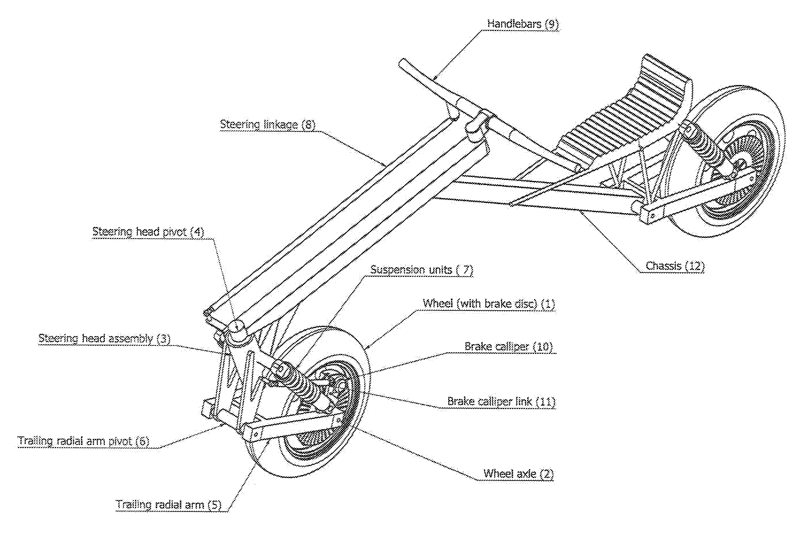
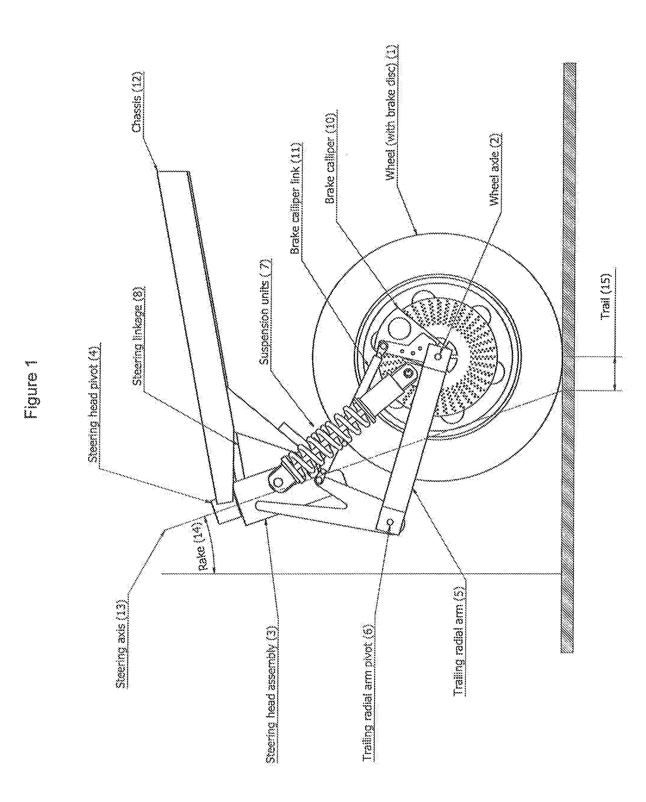
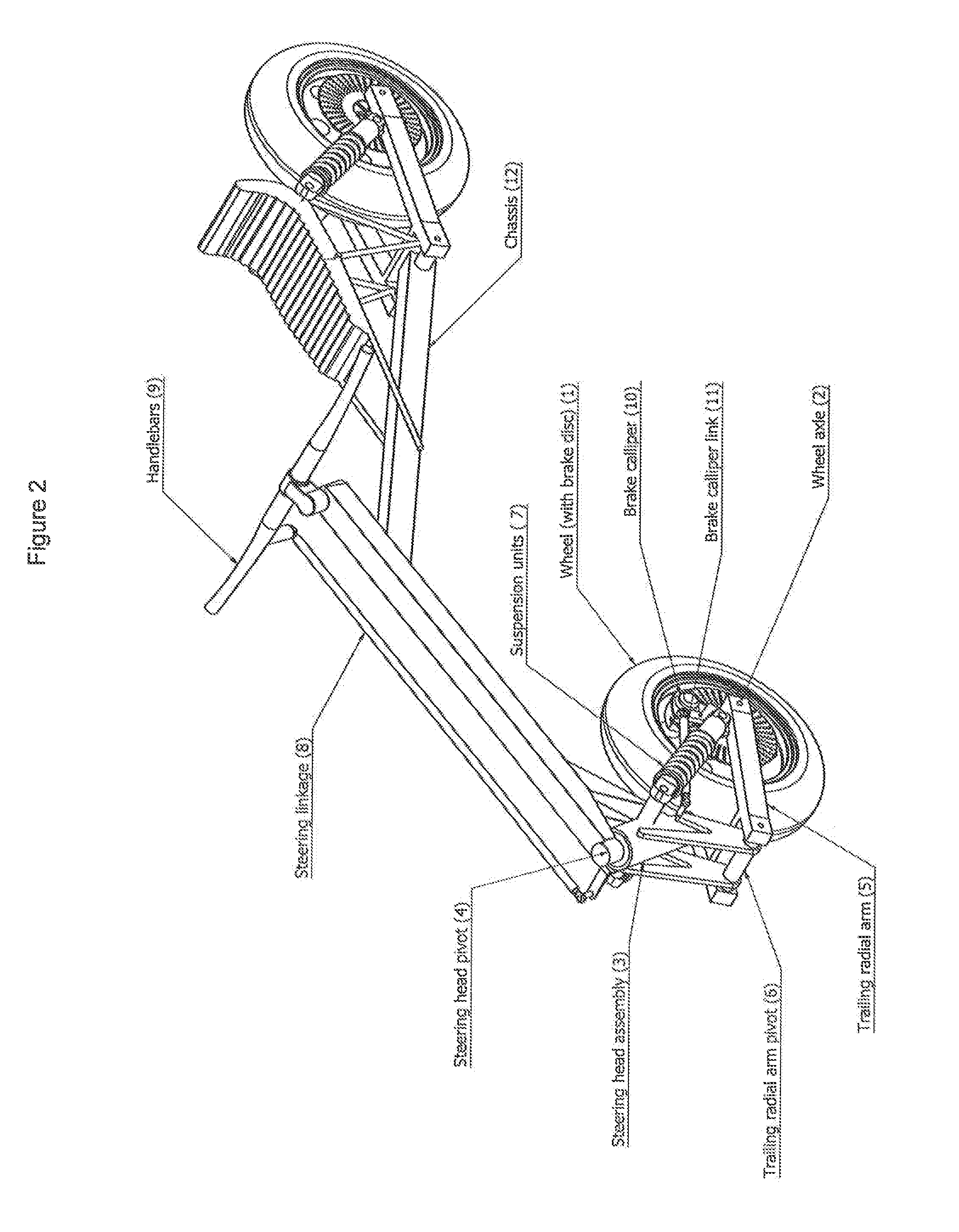
[0017]The figures show a steering and suspension system comprising front wheel assembly comprising a wheel with brake disc 1, a steering head assembly 3, a steering head pivot 4, a trailing radial arm 5, a pivot joint 6, suspension units 7, a steering linkage 8, handlebars 9, a brake calliper 10, a brake calliper link 11 and a chassis 12.

[0018]The trailing radial arm 5 is connected to the wheel axle 2 at one end and to the steering head assembly 3 at the other end. The trailing radial arm 5 and the steering head assembly 3 are joined by an approximately horizontal, pivot joint 6. The steering head assembly 3 is connected to the motorbike chassis 12 at the steering head pivot 4 which acts as an inclined pivot joint. The inclined pivot joint defines the angle or rake and position of the steering axis 13. The rake 14 and trail 15 are in turn defined by the geometry of the above components. The suspension units 7 are fitted between the live end of the radial arm 5 and the steering head ...


PUM


Abstract

A steering and suspension mechanism for a motorbike, scooter, bicycle, skateboard or other two wheeled, in-line, vehicle, incorporating a steering axis rake that is inclined to the vertical, in a direction that is upwards and forwards from the ground in the normal direction of travel, together with a trailing radial arm suspension, in combination. Steering may be effected via a push rod attached to the handlebars, which in turn pivot on the main chassis. A brake calliper may be pivoted on the wheel axle, with a link to the steering head assembly to prevent rotation of the calliper with the brake disc under braking. This link may be parallel or nearly parallel to the radial arm. The exact angle can be chosen to control ‘dive’ due to weight shift under braking.

Description

[0001]This application claims priority from British patent application serial no. 1316986.7 filed Sep. 25, 2013, which claims priority from British patent application serial no. 1310130,8 filed Jun. 7, 2013.FIELD OF THE INVENTION[0002]The present invention is a steering and suspension mechanism for a motorbike, scooter, bicycle, skateboard or other two wheeled, in-line, vehicle.BACKGROUND OF THE INVENTION[0003]Conventional motorbikes, scooters, bicycles and in-line skateboards, incorporate a steering geometry with a rake and trail. That is, the axis about which the front wheel steers is inclined to the vertical (the rake) and meets the ground at a certain distance (the trail) ahead of the position where the wheel touches the ground. Together, these features strongly influence the stability of the machine. On conventional bikes the angle of the steering axis is inclined to the vertical, leaning upwards, and rearwards from the ground.[0004]However, there are certain advantages in usin...

Claims


Application Information

Patent Timeline
Patent Type & Authority Applications(United States)
IPC IPC(8): B62K25/16B62L1/00B62K21/18
CPCB62K25/16B62L1/005B62K21/18B62K21/00B62K21/005B62K21/08B62K25/24A63C17/011
Inventor WALTON, ROBERT CHRISTOPHER
Owner WALTON ROBERT CHRISTOPHER
Why Eureka
Try Eureka