Truss spacer

Inactive Publication Date: 2012-07-19
TALLMADGE SPINNING & METAL
View PDF7 Cites 19 Cited by
  • Summary
  • Abstract
  • Description
  • Claims
  • Application Information

AI Technical Summary

Benefits of technology

[0016]FIG. 3 is an enlarged top view of the spacer with portions cut away.
[0017]

Problems solved by technology

However, many of these spacers leave much to be desired.
Many of the spacers that are available are difficult to work with while the construction worker or roofer is attempting to build this roofing structure.
While this truss spacer has its advantages, one of the disadvantages is the necessity of hammering in the integrally formed nails in order to secure

Method used


Image

  • Truss spacer
  • Truss spacer
  • Truss spacer

Examples


Embodiment Construction

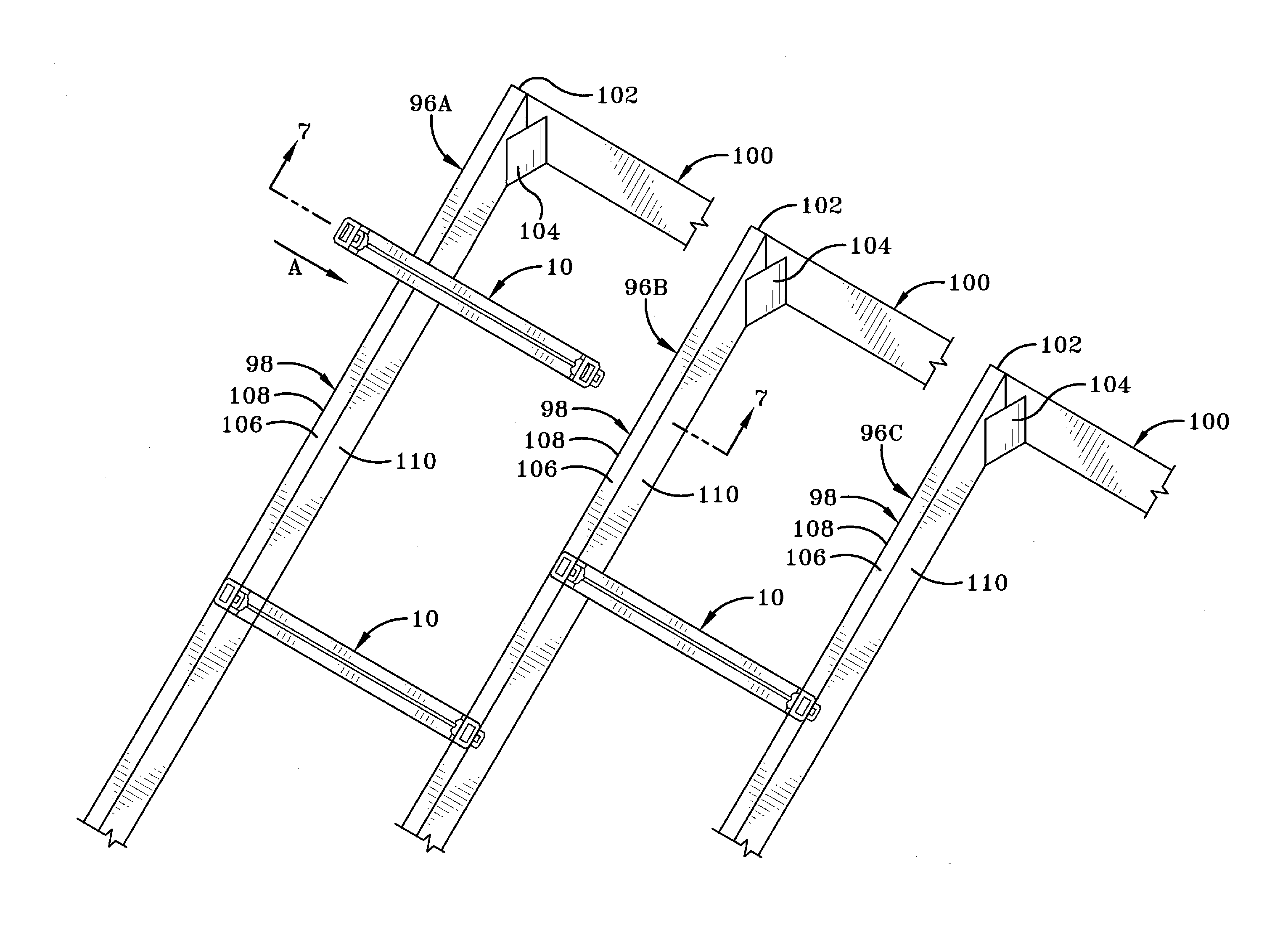
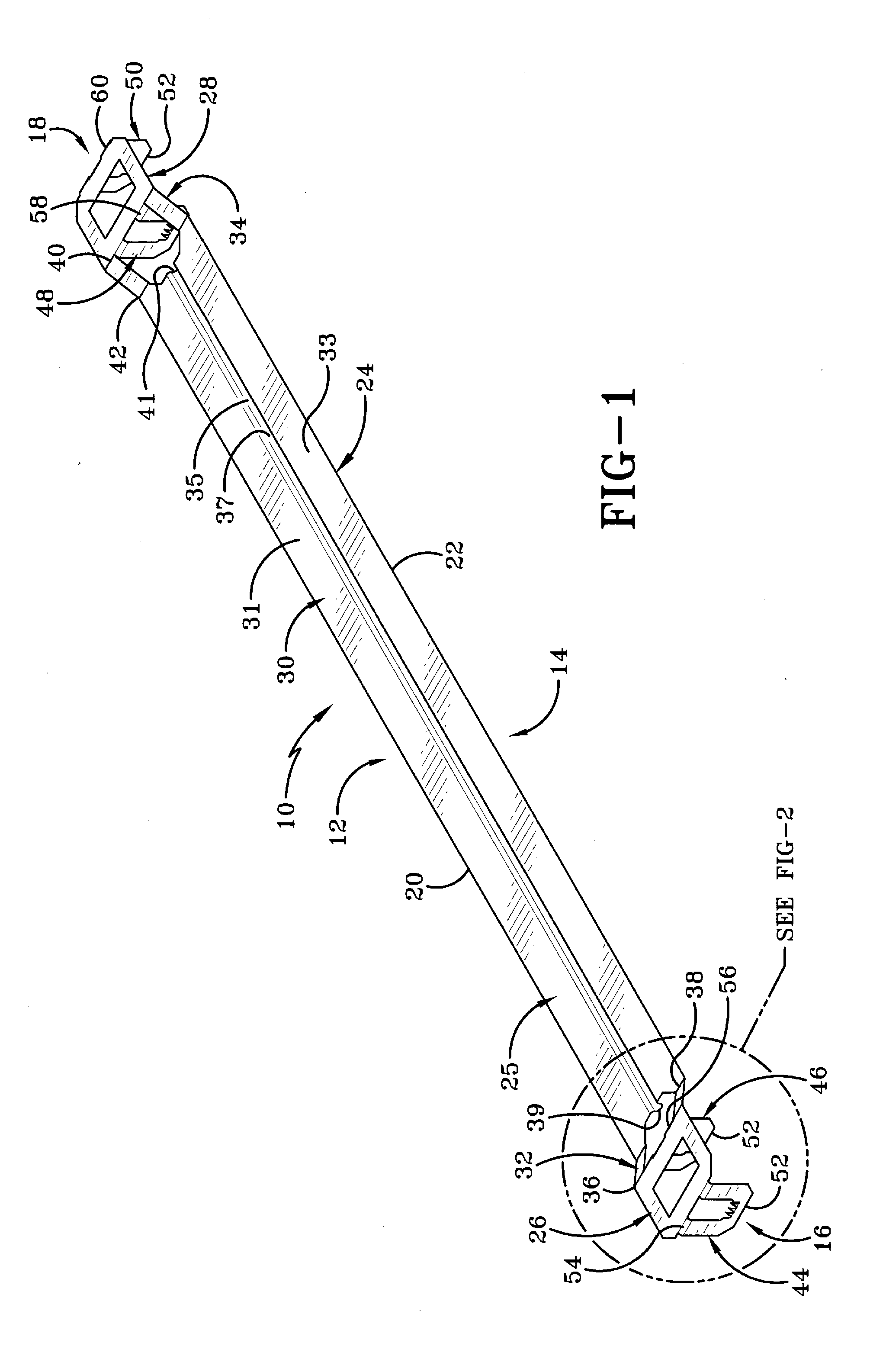
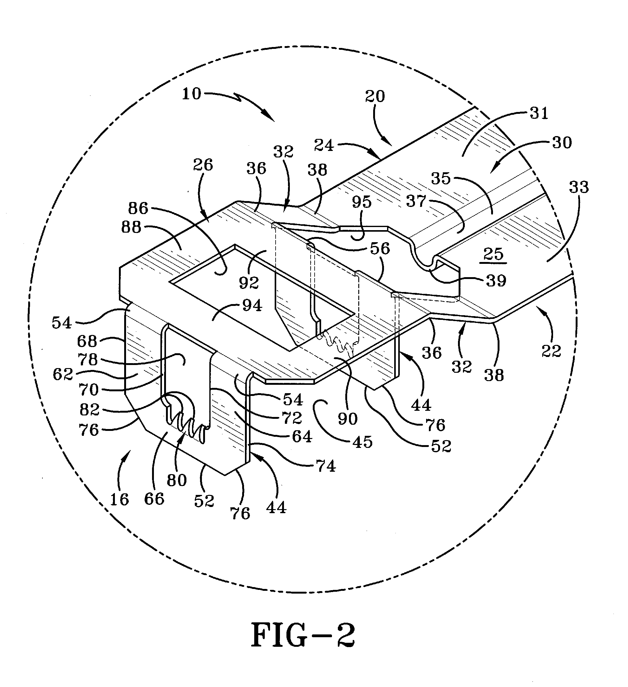
[0024]The truss spacer or spacer bar of the present invention is shown generally at 10 in FIG. 1. Spacer 10 is used to set the spacing between adjacent pairs of roof trusses during the building or installation of a roof, as will be described in greater detail further below. Spacer 10 is formed of a rigid material which is most typically metal. In the exemplary embodiment, spacer 10 in its entirety is formed from a single piece of sheet metal which is stamped and bent to form the various structures specified below. Spacer 10 is in the exemplary embodiment thus an integrally formed one-piece member. Spacer 10 has a top 12, a bottom 14, first and second opposed ends 16 and 18 defining therebetween a longitudinal direction of the spacer, and left and right sides 20 and 22 defining therebetween an axial direction of the spacer. Ends 16 and 18 define therebetween a length L1 which may vary depending on the specific spacer desired. In the exemplary embodiment, length L1 is on the order of ...


PUM


Abstract

A truss spacer and method of use to set spacing between trusses is detailed. The truss spacer typically includes teeth which grip trusses to secure the truss spacer thereto. The truss spacer may also include a central segment which is spaced downwardly between the trusses so provide a space above the central segment to receive the tips of roofing nails so that the roofing nails do not contact the central segment.

Description

CROSS REFERENCE TO RELATED APPLICATIONS[0001]This applications claims priority from U.S. Provisional Patent Application Ser. No. 61 / 414,640, filed Nov. 17, 2010; the disclosure of which is incorporated herein by referenced.BACKGROUND OF THE INVENTION[0002]1. Technical Field[0003]The present invention is related generally to construction and the roof supporting structure of a house or the like. More particularly, the invention relates to a spacer for spacing structural members in the form of roof trusses. Specifically, the present invention provides such a spacer which is simple to use and does not require nails or other separate fasteners for securing the spacer to the trusses.[0004]2. Background Information[0005]It is well known in the art to provide various types of spacer bars or the like in order to space adjacent trusses of a roof or other structural members from one another. However, many of these spacers leave much to be desired. In building a roof structure with preassembled...

Claims


Application Information

Patent Timeline
IPC IPC(8): E04G25/00E04B1/38
CPCE04G21/1891E04C2003/026
Inventor NOTURNO, SAM P.
Owner TALLMADGE SPINNING & METAL
Why Eureka
Try Eureka