Semiconductor device having seal wiring
a technology of sealing wire and semiconductor devices, which is applied in the direction of semiconductor devices, semiconductor/solid-state device details, electrical equipment, etc., can solve the problems of insufficient impact prevention of passivation films, cracks, etc., and achieve the effect of preventing cracks, preventing chipping, and preventing degradation of reliability and moisture resistance of semiconductor devices
- Summary
- Abstract
- Description
- Claims
- Application Information
AI Technical Summary
Benefits of technology
Problems solved by technology
Method used
Image
Examples
first embodiment
[0078]Hereinafter, a semiconductor device and a manufacturing method thereof according to a first embodiment of the invention will be described with reference to the figures.
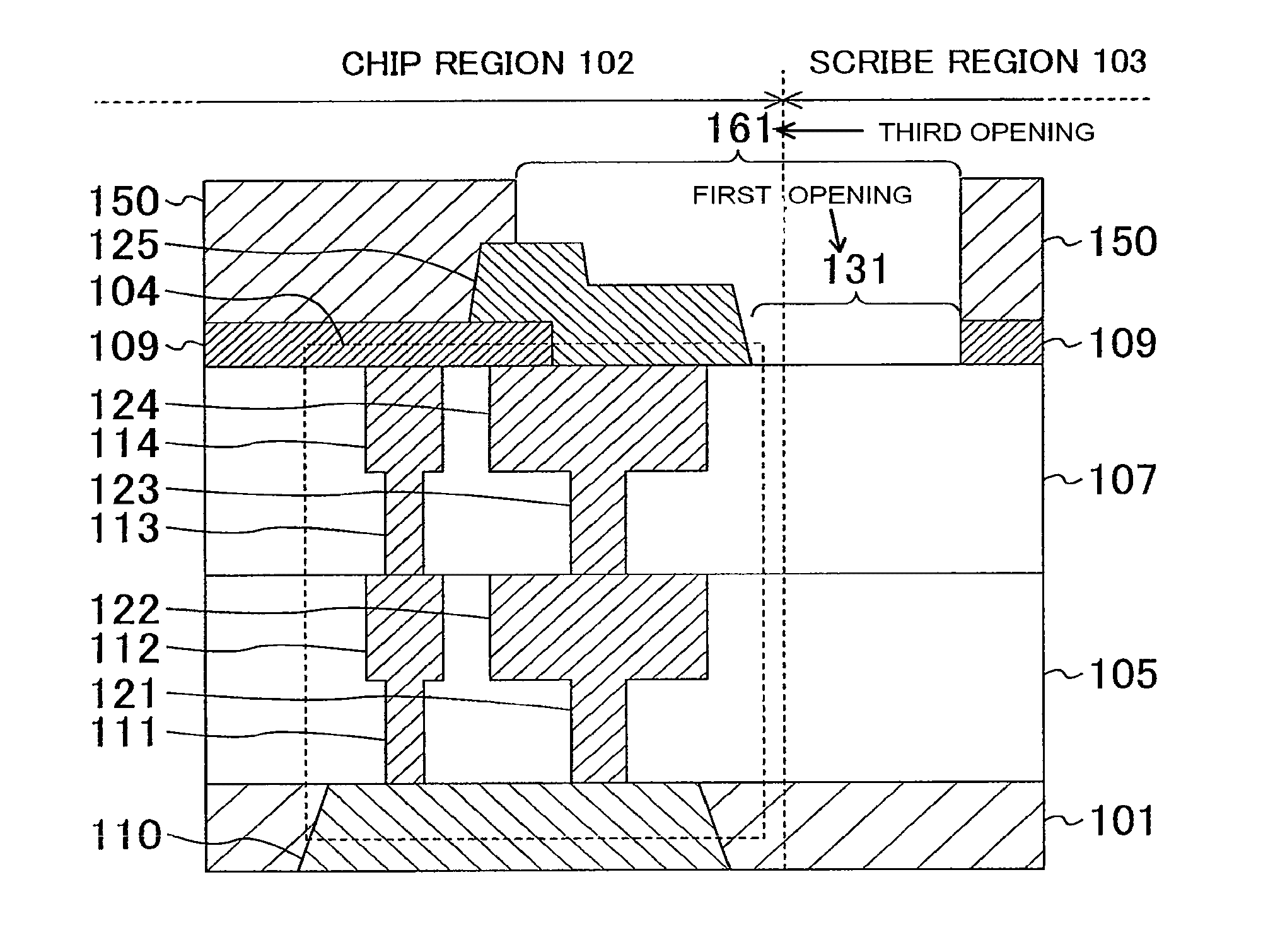
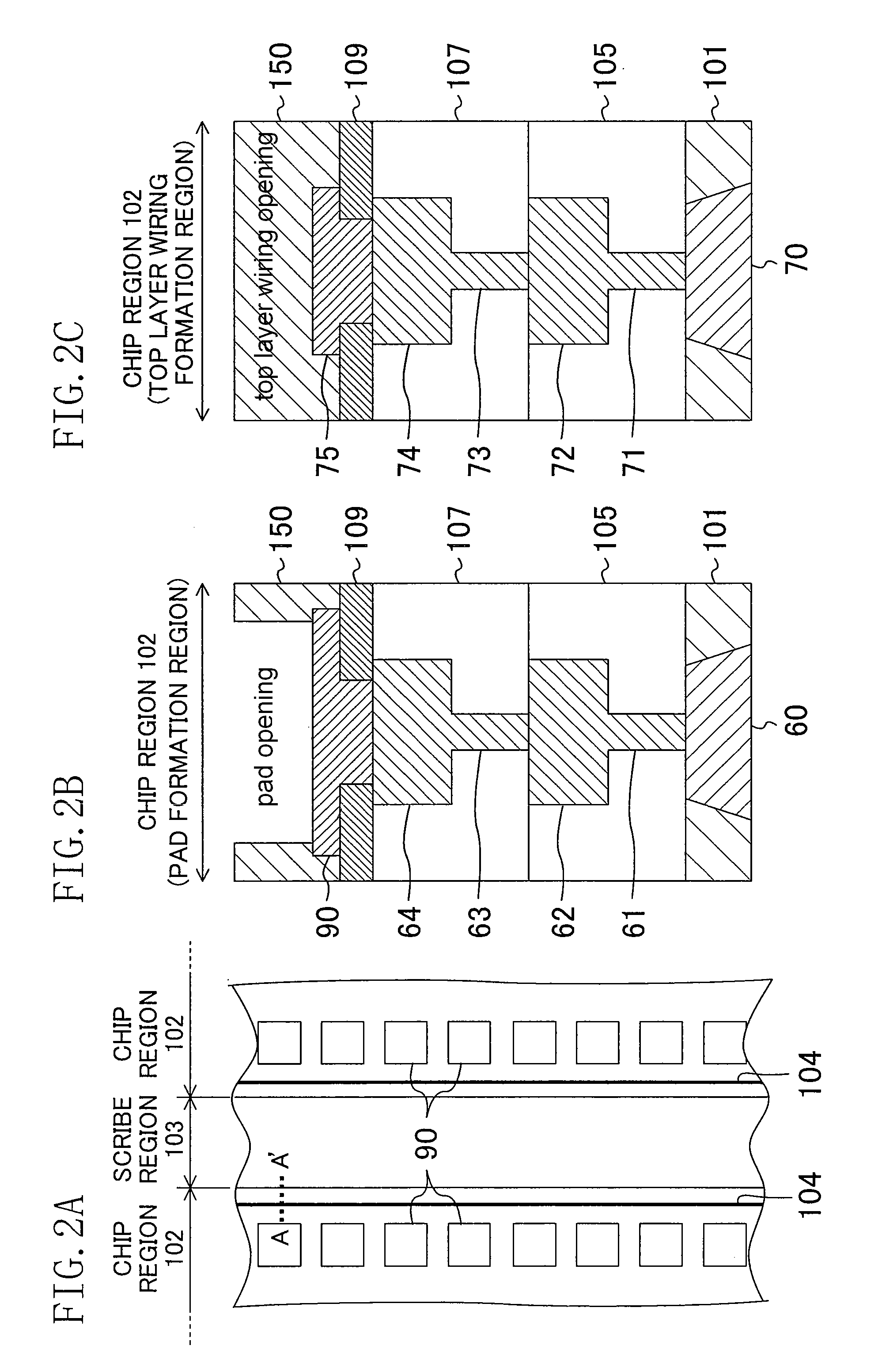
[0079]FIG. 3 shows a cross-sectional structure of an end portion of a semiconductor device (more specifically, a diced chip) according to the first embodiment. More specifically, FIG. 3 shows a cross-sectional structure of an end portion of a semiconductor device including a seal ring 104 formed in the periphery of the chip region 102. FIG. 3 is a cross-sectional view taken along line A-A′ in FIG. 2A.
[0080]As shown in FIG. 3, a chip region 102 is formed adjacent to a scribe region 103 on a substrate 101. A first interlayer insulating film 105 and a second interlayer insulating film 107 are sequentially formed on the substrate 101. A seal ring 104 is formed in the layered structure of the interlayer insulating films 105 and 107. The seal ring 104 extends through this layered structure and continuously surrounds t...
second embodiment
[0151]Hereinafter, a semiconductor device and a manufacturing method thereof according to a second embodiment of the invention will be described with reference to the figures.
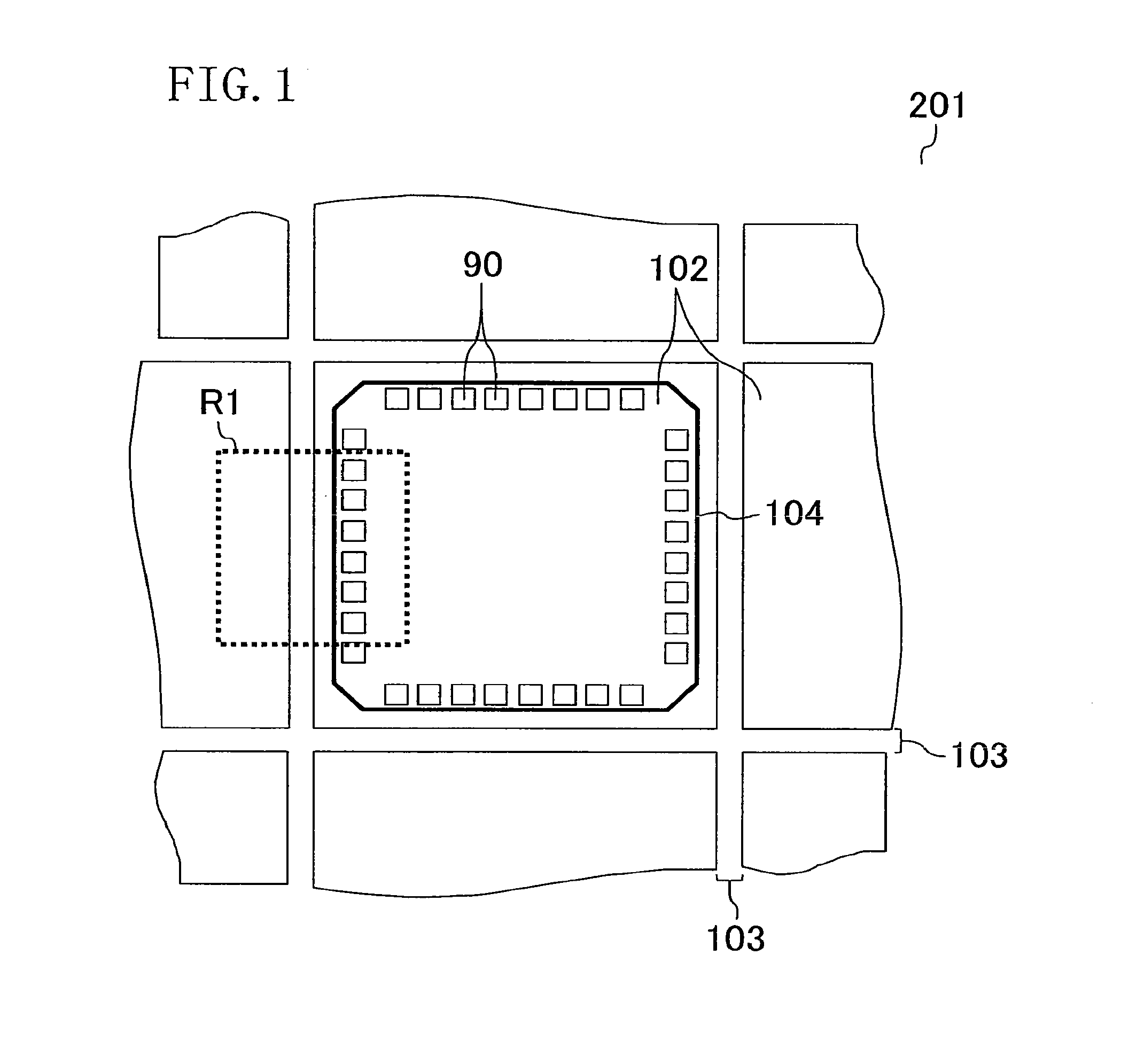
[0152]FIG. 11 shows a cross-sectional structure of an end portion of a semiconductor device (more specifically, a diced chip) according to the second embodiment. More specifically, FIG. 11 shows a cross-sectional structure of an end portion of a semiconductor device including a seal ring 104 formed in the periphery of the chip region 102 as shown in FIG. 1. FIG. 11 is a cross-sectional view taken along line A-A′ in FIG. 2A. In FIG. 11, the same elements as those of the semiconductor device of the first embodiment shown in FIG. 3 are denoted with the same reference numerals and description thereof will be omitted as appropriate.
[0153]This embodiment is different from the first embodiment in the following points: as shown in FIG. 11, the first passivation film 109 has an opening 132 in addition to the opening 131...
third embodiment
[0191]Hereinafter, a semiconductor device and a manufacturing method thereof according to a third embodiment of the invention will be described with reference to the figures.
[0192]FIG. 18 shows a cross-sectional structure of an end portion of a semiconductor device (more specifically, a diced chip) according to the third embodiment. More specifically, FIG. 18 shows a cross-sectional structure of an end portion of a semiconductor device including a seal ring 104 formed in the periphery of the chip region 102 as shown in FIG. 1. FIG. 18 is a cross-sectional view taken along line A-A′ in FIG. 2A. In FIG. 18, the same elements as those of the semiconductor device of the first embodiment shown in FIG. 3 are denoted with the same reference numerals and description thereof will be omitted as appropriate.
[0193]This embodiment is different from the first embodiment in the following points: as shown in FIG. 18, the first passivation film 109 has an opening 132 in addition to the opening 131 l...
PUM
 Abstract
Description
Claims
Application Information
 - R&D
- Intellectual Property
- Life Sciences
- Materials
- Tech Scout
- Unparalleled Data Quality
- Higher Quality Content
- 60% Fewer Hallucinations
Browse by: Latest US Patents, China's latest patents, Technical Efficacy Thesaurus, Application Domain, Technology Topic, Popular Technical Reports.
© 2025 PatSnap. All rights reserved.Legal|Privacy policy|Modern Slavery Act Transparency Statement|Sitemap|About US| Contact US: help@patsnap.com


