Aligning device for printing member in printer

Inactive Publication Date: 2012-07-19
SATO HLDG CORP
View PDF4 Cites 3 Cited by
  • Summary
  • Abstract
  • Description
  • Claims
  • Application Information

AI Technical Summary

Benefits of technology

[0025]According to the aligning device for the printing member in the printer of the present invention, an attachment tubular shaft having a cylindrical shaft and a one-side contact circular plate is provided, in the cylindrical shaft, with a pinion rotatably disposed on a center line across a width direction of the transfer path and a pair of racks extending along an axial direction of the cylindrical shaft and being engaged with the pinion such that the pair of racks are movable in opposite directions from each other, and a push-in projection drives the racks and the pinion by pushing a core tube toward a push-in end of the cylindrical shaft, and whereby the core tube can be positioned at a central position across the width direction of the transfer path. Therefore, it is possible to use the center alignment as needed while the one-end supporting structure is employed.
[0026]In addition, an operation of attachment of the core tube to the cylindrical shaft of the attachment shaft is the same in both the one-end supporting and the center alignment, and a user of the printer need not learn a new or different operation procedures.
[0027]Further, taking the compatibility of printing data into account, it is possible to maintain the balance of a print head on the right and left and a transfer resistance at a favorable level, even when printing data that has been used in a printer of the both-end supporting or center alignment is used in a printer of the one-end supporting or one-end alignment.

Problems solved by technology

However, as the structure is complicated, there are problems of inconvenience in assembly and increased cost, and a problem that loading of the printing member becomes cumbersome.
On the other hand, in the one-end supporting, as the printing paper or the ribbon is aligned on one end, the print head in the printing unit is relatively unbalanced on the right and left, and the transfer resistance of the printing member is also relatively unbalanced.
This provides an adverse effect that wrinkling and meandering could easily occur, especially in the case of thin thermal transfer ribbons.
As described above, both methods of aligning the printing member by both-end supporting and one-end supporting have, in connection with the center alignment and the one-end alignment, have advantages and disadvantages in their performance and cost.
However, taking the compatibility of printing data that a printer user has used in the past into account, a user who has been using a printer with one-end supporting or one-end alignment will have to select a printer of the structure of one-end supporting or one-end alignment under relatively poor conditions, such as the imbalance of the print head on the right and left or the transfer resistance, unless the user changes a processing method of the printing data to a processing method for both-end alignment (that is, unless the user changes the processing method so as to change a portion used by the print head) when using a printer with both-end supporting.
Conversely, when a user, who has been using a printer of center alignment and has been using the both-end supporting, later replaces the printer of both-end supporting with a printer of one-end alignment, the user is adversely required to convert printing data that has been processed to be printed using a central region of the print head in accordance with the one-end alignment so as to change the used portion of the print head to a large extent.
Therefore, after starting to use a printer of one-end alignment, if the user creates new printing data and uses the printer based on the printing data, the user has to continue using the printer of one-end alignment having the above problems unless entirely converting the printing data into data in accordance with the center alignment.

Method used


Image

  • Aligning device for printing member in printer
  • Aligning device for printing member in printer
  • Aligning device for printing member in printer

Examples


embodiment

[0039]The following describes the aligning device for the printing member in the printer according to an embodiment of the present invention with reference to FIG. 1 through FIG. 10, taking a thermal transfer ribbon and a continuous label body as examples of the printing member.

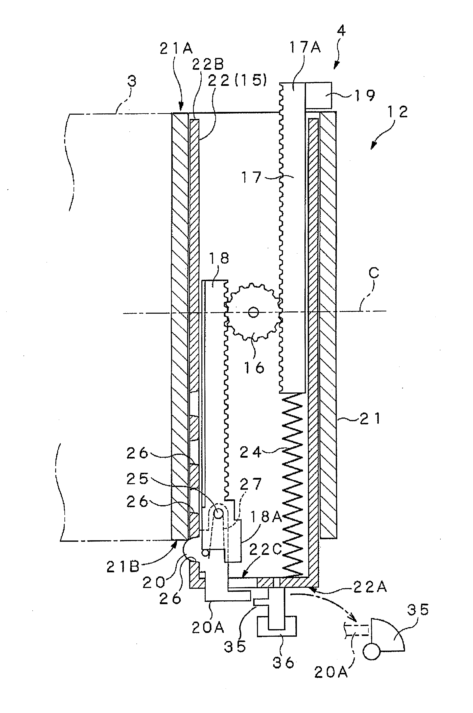
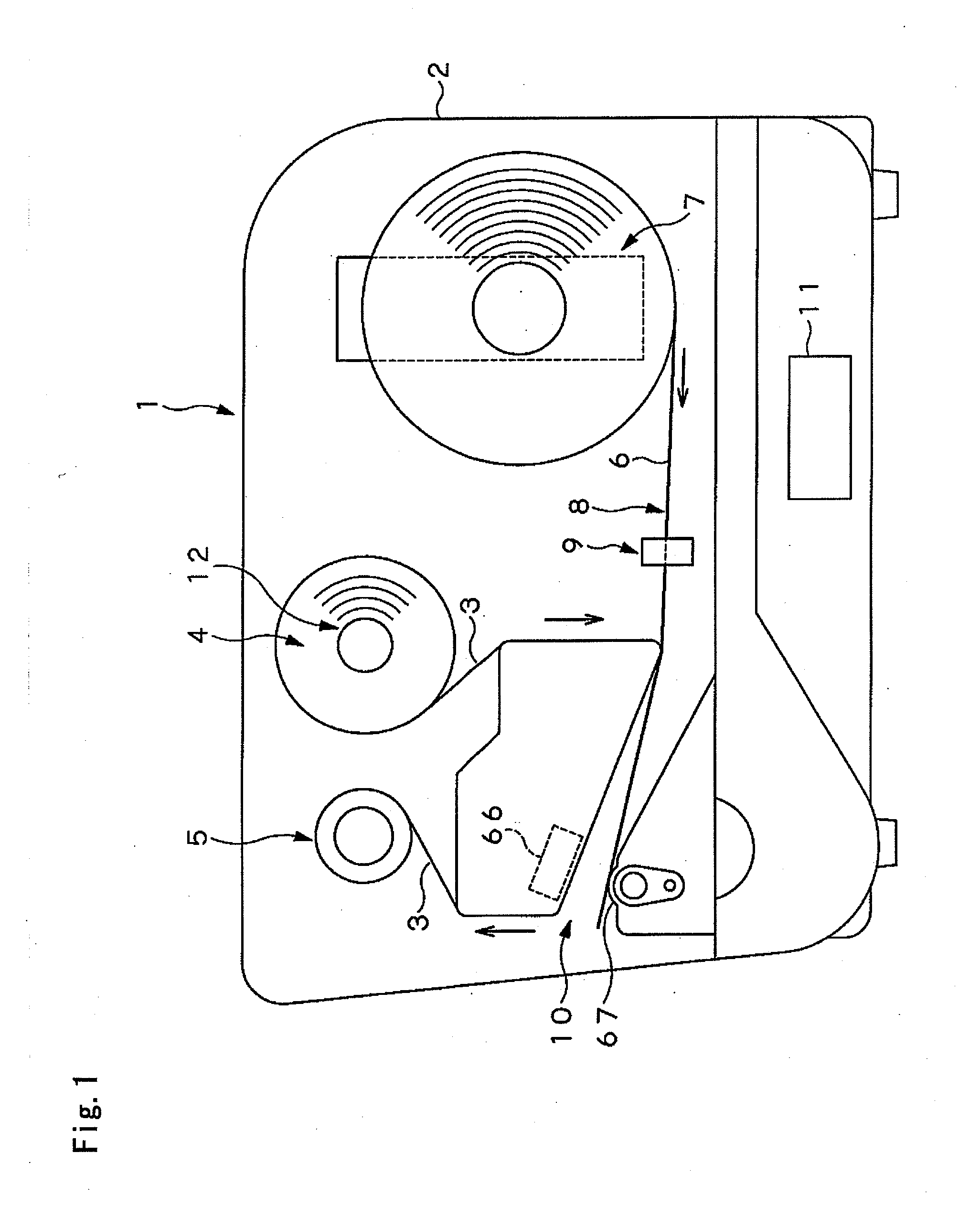
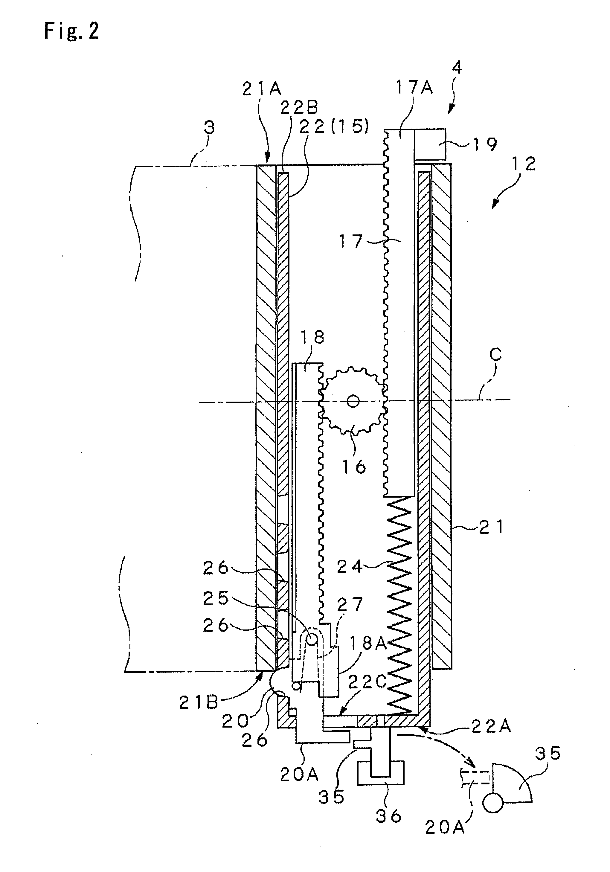
[0040]FIG. 1 is a side view schematically illustrating the printer (thermal printer 1). The thermal printer 1 is provided with a printer housing 2, a supplying unit 4 configured to hold a rolled thermal transfer ribbon 3 in a one-end supporting manner, a winding unit 5 for the thermal transfer ribbon 3, a supplying unit 7 configured to hold a rolled continuous label body 6 in the one-end supporting manner, a transfer path 8, a label guiding unit 9 disposed in the middle of the transfer path 8, a printing unit 10, and a controlling unit 11.

[0041]In the printer housing 2, the thermal transfer ribbon 3 is held by the supplying unit 4 in the one-end supporting manner, and the continuous label body 6 is held by th...


PUM


Abstract

An aligning device for a printing member in a printer in which it is presupposed to use a printer of a one-end supporting structure. The printing member, such as a thermal transfer ribbon 3, can be used by selecting one of center alignment and one-end alignment. A rack and pinion structure within a cylindrical shaft 22 includes a pinion 16 rotatably provided within the cylindrical shaft 22, a pair of racks 17 and 18, a push-in projection 19 configured to push one rack 17 toward the push-in end 22B of the cylindrical shaft 22. A positioning projection 20 is configured to detachably engage with any of a plurality of positioning engagement holes 26 defined in the cylindrical shaft 22 along an axial direction. The push-in projection 19 drives the racks 17 and 18 and the pinion 16 by the pushing of the core tube 21 to the cylindrical shaft 22, and the positioning projection 20 engages with one of the positioning engagement holes 26 in the cylindrical shaft 22, to position the core tube 21 at the central position across the width direction.

Description

[0001]The present application is a 35 U.S.C. §§371 national phase conversion of PCT / JP2010 / 001039, filed Feb. 18, 2010, which claims priority of Japanese Application No. 2009-298652, filed Dec. 28, 2009, the contents of which are incorporated by reference herein. The PCT International Application was published in the Japanese language.TECHNICAL FIELD[0002]The present invention relates to an aligning device for a printing member in a printer, and, in particular, to an aligning device for a printing member in a printer capable of feeding a printing member, such as rolled printing paper or an ink ribbon and a thermal transfer ribbon, to a transfer path in a strip, and of printing information of a predetermined content using the printing member.BACKGROUND ART[0003]Conventionally, in various types of printers, a printing member is loaded on and held by a supplying unit (such as a paper core and a ribbon core) for a printing member, such as printing paper or an ink ribbon and a thermal tr...

Claims


Application Information

Patent Timeline
IPC IPC(8): B41J17/28
CPCB41J33/14B41J15/046B41J15/02B65H75/241
Inventor KOKUTA, HIROSHI
Owner SATO HLDG CORP
Why Eureka
Try Eureka