Supercharge Your Innovation With Domain-Expert AI Agents!

Electrical contact for interconnect member

a technology of electrical contacts and interconnect members, which is applied in the direction of coupling contact members, coupling device connections, electrical apparatus construction details, etc., can solve the problems of increasing the stress that builds within the contact, affecting the working range and disadvantages of known compressible contacts

Active Publication Date: 2012-07-19
TYCO ELECTRONICS LOGISTICS AG (CH)
View PDF3 Cites 6 Cited by
  • Summary
  • Abstract
  • Description
  • Claims
  • Application Information

AI Technical Summary

Benefits of technology

The patent text describes an electrical contact that has an integrally-formed body with a mating segment, mounting segment, and a pair of arms that connect the mating and mounting segments. The arms extend along helical paths, and the contact can be used to connect electrical components. The technical effect of this design is that it provides a reliable and secure electrical connection that can withstand high levels of current and voltage.

Problems solved by technology

But, known compressible contacts of interconnect members suffer from disadvantages when used with an increased number and / or density of mating contacts on the electrical components.
For example, known compressible contacts may have a limited working range.
Additionally, the contact force required to compress known contacts may be higher than is desired, which may increase the stresses that build within the contact during compression thereof.
The increased stresses may cause the contact to fatigue and thereby fail.
Moreover, the increased stresses within the contact may limit the number of mating cycles of the contact and / or may limit the working range of the contact even further.

Method used


Image

  • Electrical contact for interconnect member
  • Electrical contact for interconnect member
  • Electrical contact for interconnect member

Examples


Embodiment Construction

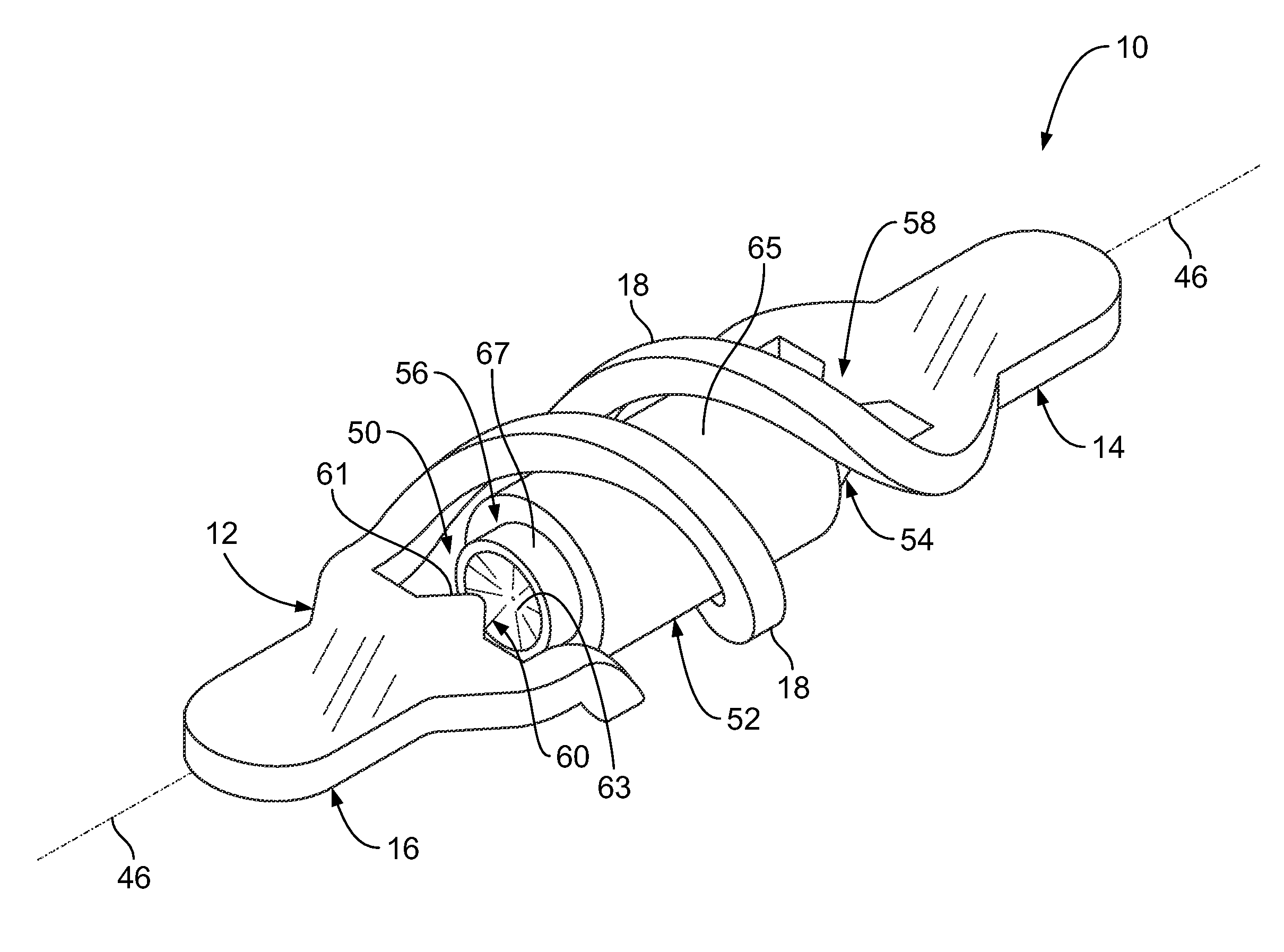
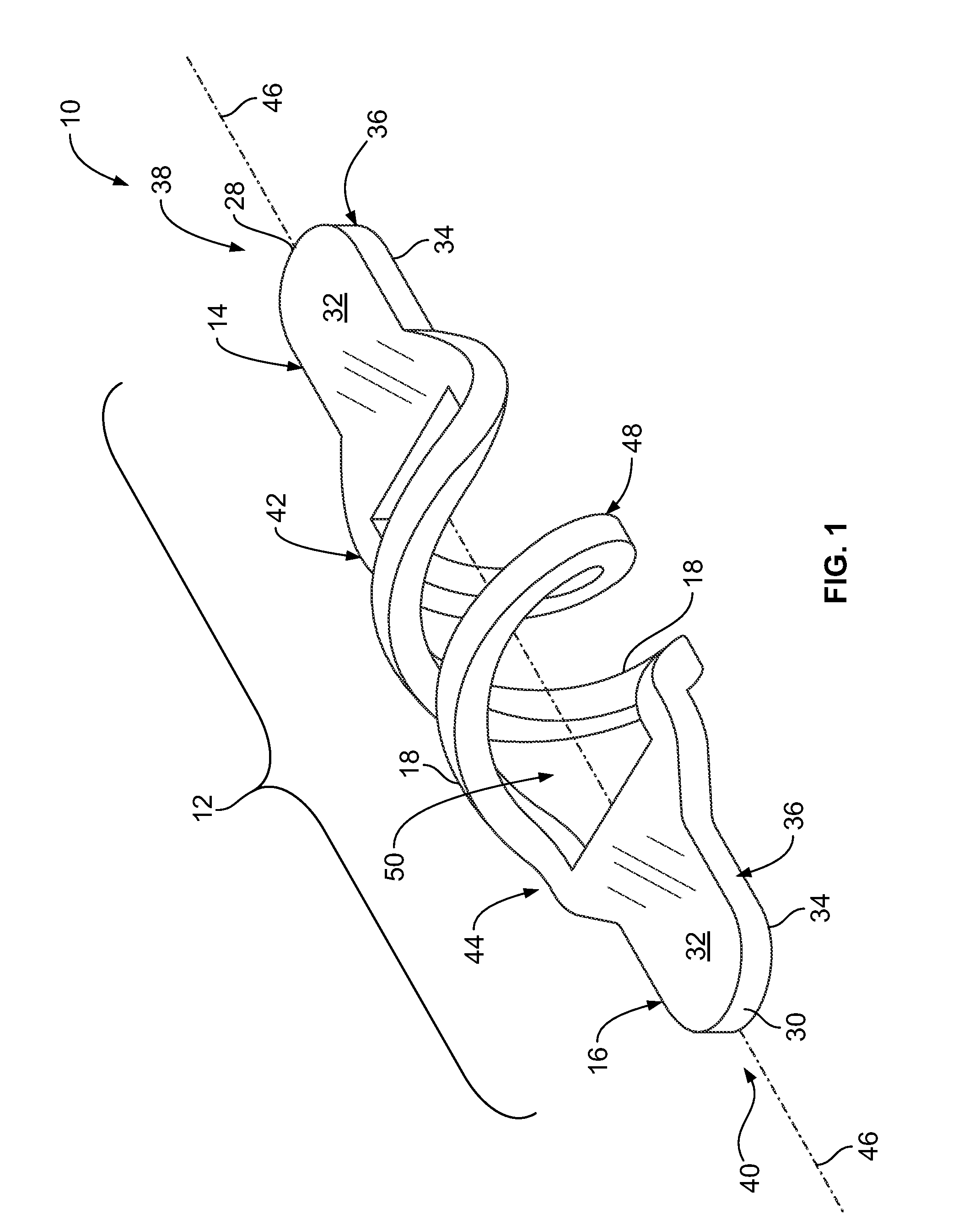
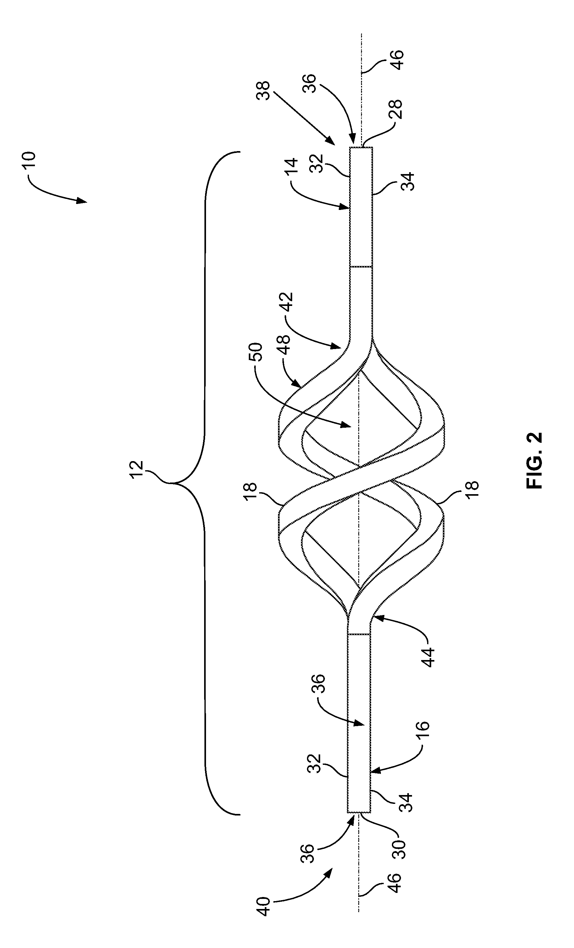
[0018]FIG. 1 is a perspective view of an exemplary embodiment of an electrical contact 10. FIG. 2 is a side elevational view of the electrical contact 10. Referring now to FIGS. 1 and 2, the electrical contact 10 includes a body 12, which includes a mating segment 14, a mating segment 16, and one or more arms 18. The arms 18 extend from the mating segment 14 to the mounting segment 16, and vice versa, to interconnect the mating segments 14 and 16. In other words, the arms 18 mechanically connect the mating segment 14 to the mating segment 16. The arms 18 also electrically connect the mating segments 14 and 16 together. As will be described in more detail below, the arms 18 extend along helical paths for at least some distance as the arms 18 extend from the mating segment 14 to the mating segment 16, and vice versa. The mating segment 14 and the mating segment 16 may each be referred to herein as a “mounting segment”.

[0019]The body 12 of the electrical contact 10 is optionally integr...


PUM


Abstract

An electrical contact is provided. The electrical contact includes an integrally-formed body having a mating segment, a mounting segment, and a pair of arms interconnect the mating segment and the mounting segment. The arms extend along helical paths for at least some distance as the arms extend from the mating segment to the mounting segment.

Description

BACKGROUND OF THE INVENTION[0001]The subject matter described and / or illustrated herein relates generally to electrical contacts, and more particularly, to the electrical contacts of interconnect members that electrically interconnect electrical components.[0002]Interconnect members are sometimes used to provide electrical connection between different electrical components, such as, but not limited to, integrated circuits, electronic modules, printed circuit boards, and the like. Many of these electrical components have mating contacts arranged in a “land grid array” (LGA), which is a two-dimensional array of contact pads. One type of interconnect device, sometimes known as an “interposer”, has an array of compressible contacts which is placed between the two opposing arrays of the electrical components to provide an electrical connection between the mating contacts of the opposing arrays.[0003]Competition and market demands have continued the trend toward smaller and higher perform...

Claims


Application Information

Patent Timeline
Patent Type & Authority Applications(United States)
IPC IPC(8): H01R13/02
CPCH01R12/7082H05K7/1061H01R13/2421
Inventor ALDEN, III, WAYNE STEWEARTMASON, JEFFERY WALTERMURPHY, WILLIAM BRIAN
Owner TYCO ELECTRONICS LOGISTICS AG (CH)
Features
  • R&D
  • Intellectual Property
  • Life Sciences
  • Materials
  • Tech Scout
  • Unparalleled Data Quality
  • Higher Quality Content
  • 60% Fewer Hallucinations
Learn More