
Hydraulic fracture diverter apparatus and method thereof

a technology of hydraulic fracture and diverter, which is applied in the direction of fluid removal, sealing/packing, and wellbore/well accessories, etc., can solve the problems of complex and subject to failur

Active Publication Date: 2012-09-20
BAKER HUGHES INC
View PDF24 Cites 37 Cited by
  • Summary
  • Abstract
  • Description
  • Claims
  • Application Information

AI Technical Summary

Problems solved by technology

Conventionally, hydraulic-set or swelling packers have been used to divert such proppant, however these can be complicated and subject to failure.

Method used


Image

  • Hydraulic fracture diverter apparatus and method thereof
  • Hydraulic fracture diverter apparatus and method thereof

Examples


Embodiment Construction

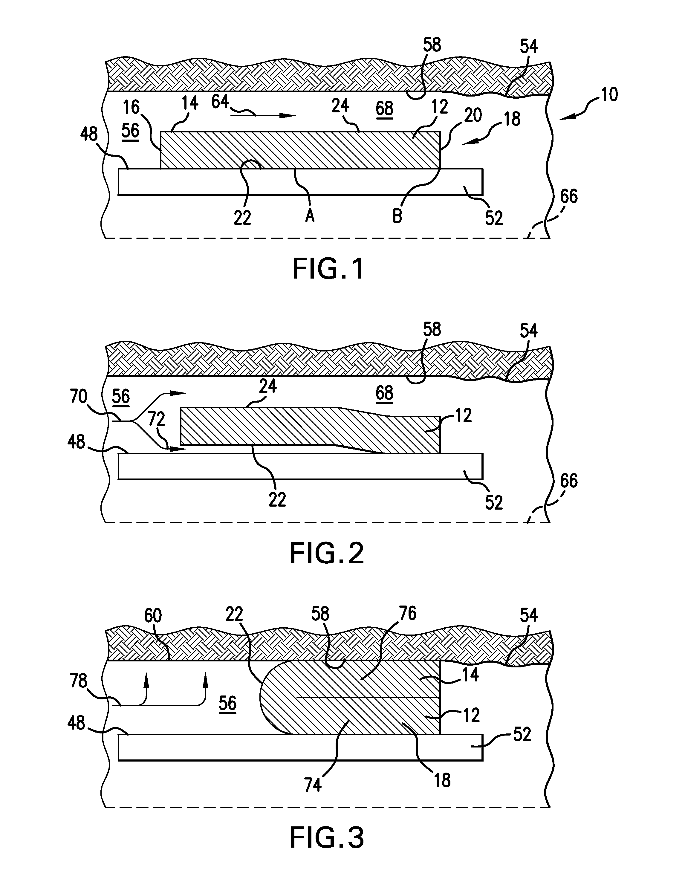
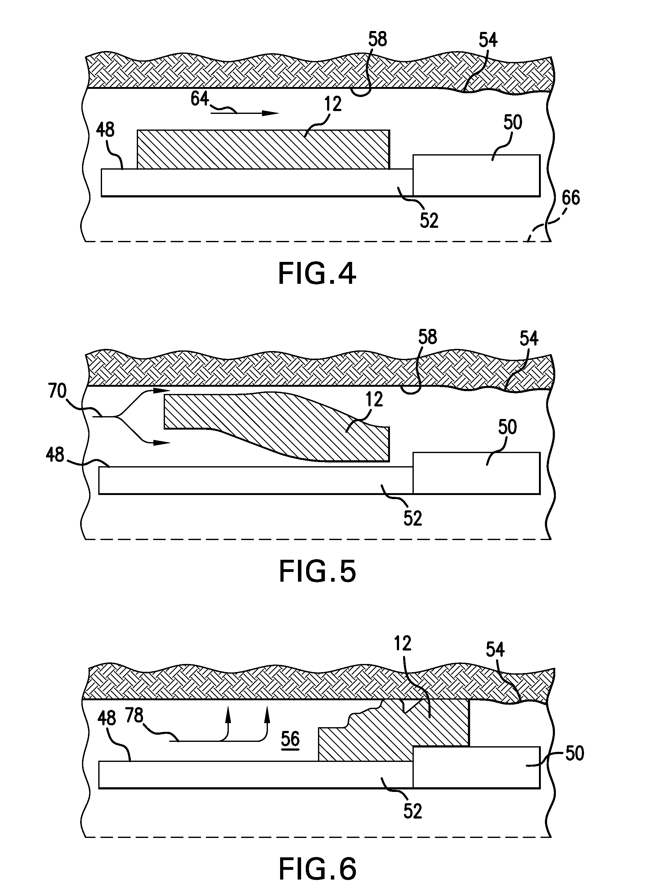
[0011]A detailed description of one or more embodiments of the disclosed apparatus and method are presented herein by way of exemplification and not limitation with reference to the Figures.

[0012]With reference to FIG. 1, a pipe string 52 is shown positioned within a wellbore 54. The pipe string 52 includes an outer surface 48 spaced from a formation face 58 of the wellbore 54, and a first annulus 56 is formed between the pipe string 52 and the formation face 58 of the wellbore 54. In a non-plugged condition, flow 64 is able to pass through the first annulus 56, past the pipe string 52 within the wellbore 54.

[0013]In one exemplary embodiment, a hydraulic fracture diverter apparatus 10 includes a substantially flexible cylindrical or tubular element 12. The element 12 includes a first end 14 adjacent a first end face 16 and a second end 18 adjacent a second end face 20. The first end 14 may be an upstream end where the first end face 16 faces the flow 64 and the second end 18 may be ...


PUM


Abstract

An apparatus positionable along a downhole string. The apparatus includes a flexible structure retained on a surface of the string in a first condition. The flexible structure movable by a flow to substantially fill an annular space between the string and a radially positioned structure in a second condition. A method of diverting fracturing treatments in a wellbore is also included.

Description

BACKGROUND[0001]In recent technology related to downhole drilling and completion, fracturing has become more prevalent. Fractures are created mostly from pressure, however sometimes there will be proppant in the slurry used to pressurize the well and that proppant flows into the fractures once open to maintain the fractures in an open condition. Conventionally, hydraulic-set or swelling packers have been used to divert such proppant, however these can be complicated and subject to failure. Since causing and maintaining fractures to be preferentially in zones of interest is desirable, the art is always receptive to new concepts related thereto.BRIEF DESCRIPTION[0002]An apparatus positionable along a downhole string, the apparatus includes a flexible structure retained on a surface of the string in a first condition, the flexible structure movable by a flow to substantially fill an annular space between the string and a radially positioned structure in a second condition.[0003]A metho...

Claims


Application Information

Patent Timeline
Patent Type & Authority Applications(United States)
IPC IPC(8): E21B43/26
CPCE21B43/26E21B33/1208
Inventor O'MALLEY, EDWARD J.SOLFRONK, MATTHEW D.
Owner BAKER HUGHES INC
Learn More