
System and Method for Automatic Fueling of Hydraulic Fracturing and Other Oilfield Equipment

a technology of hydraulic fracturing and automatic fueling, which is applied in the direction of transportation and packaging, liquid transfer devices, and borehole/well accessories, etc., can solve the problems of difficulty in keeping over a dozen pieces of equipment operating at different pressures, fracturing hydrocarbon wells that require a great amount of pressure, and requiring fracturing time and money

Active Publication Date: 2019-04-25
AMERICAN ENERGY INNOVATIONS LLC
View PDF0 Cites 154 Cited by
  • Summary
  • Abstract
  • Description
  • Claims
  • Application Information

AI Technical Summary

Benefits of technology

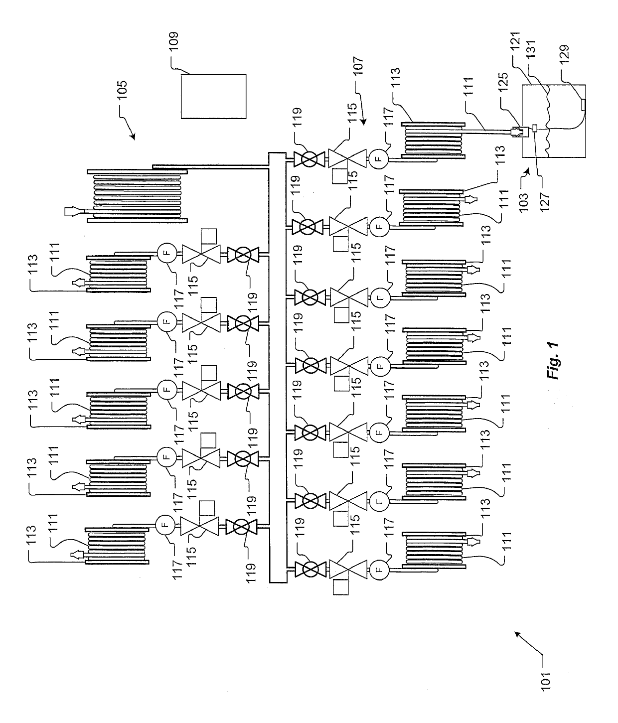
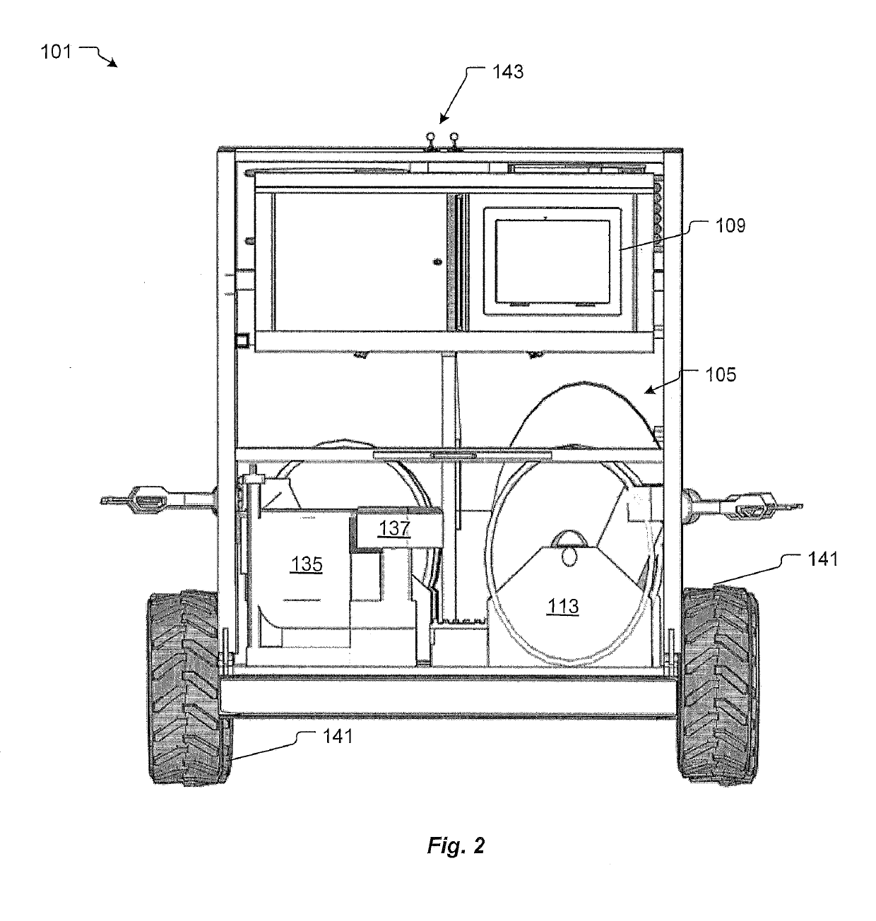
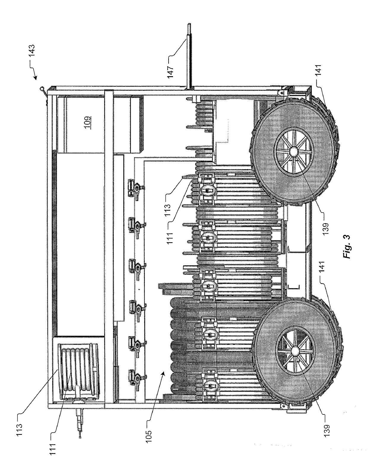
The present invention is a system and method for automatically fueling hydraulic fracturing equipment in real-time, with the ability to report fuel tank status, usage, and fill level. The system is designed to overcome the shortcomings of conventional systems, such as stopping to refuel equipment and keeping multiple hoses snaked in and around the pumps and trailers. The system includes a controller screen and a system for automatically fueling equipment with the ability to report fuel tank status, usage, and fill level on a fuel transport. The technical effects of the invention include reducing fuel costs and downtime, improving operational efficiency, and providing better data reporting.

Problems solved by technology

The fracturing of hydrocarbon wells requires great amounts of pressure.
First, stopping the frac to refill saddle tanks cost time and money.
Second, different frac pump engines require different fuel pressures to operate, and keeping over a dozen pieces of equipment operating at different pressures is difficult.
Third, the space at a fracturing site is limited and conventional systems require multiple hoses snaked in and around the pumps and various trailers.

Method used


Image

  • System and Method for Automatic Fueling of Hydraulic Fracturing and Other Oilfield Equipment
  • System and Method for Automatic Fueling of Hydraulic Fracturing and Other Oilfield Equipment
  • System and Method for Automatic Fueling of Hydraulic Fracturing and Other Oilfield Equipment

Examples


Embodiment Construction

[0025]Illustrative embodiments of the system and method for automatic fueling of hydraulic fracturing equipment with the ability to report fuel tank status, usage, and fill level are provided below. It will, of course, be appreciated that in the development of any actual embodiment, numerous implementation-specific decisions will be made to achieve the developer's specific goals, such as compliance with assembly-related and business-related constraints, which will vary from one implementation to another. Moreover, it will be appreciated that such a development effort might be complex and time-consuming, but would nevertheless be a routine undertaking for those of ordinary skill in the art having the benefit of this disclosure.

[0026]In the specification, reference may be made to the spatial relationships between various components and to the spatial orientation of various aspects of components as the devices are depicted in the attached drawings. However, as will be recognized by tho...


PUM


Abstract

A system and method for fueling multiple saddle tanks of hydraulic fracturing equipment from a single self-propelled cart. The cart having multiple retractable fuel lines for providing and obtaining fuel. Each retractable fuel supply line uses a flowmeter, a ball valve, and an electrically actuated valve to provide remote control to a controller based on a user's selected fueling requirements. An electronic reporting system provides fuel data to operators and users. Fuel data such as fuel tank status, an amount of fuel usage over a stage level, a daily level, or job level along with a fill level of the fuel tank.

Description

TECHNICAL FIELD[0001]The present invention relates generally to fueling systems for hydraulic fracturing equipment, and more specifically to a system and method for automatically fueling equipment and reporting important information in a real time for fracing hydrocarbon wells.DESCRIPTION OF THE PRIOR ART[0002]The fracturing of hydrocarbon wells requires great amounts of pressure. Diesel, natural gas, and or a combination of those driven pumps are utilized in order to generate pressures sufficient to fracture shale deposits. This equipment is located remotely and require refueling several times during a frac job. Conventional systems for fueling hydraulic fracturing equipment use trucks and pump fuel into saddle tanks from the trucks as required to keep the saddle tanks full. Alternative conventional systems bypass the saddle tanks of the hydraulic fracturing equipment and provide a pressurized fuel line and a return line for each piece of equipment. Conventionally data is monitored...

Claims


Application Information

Patent Timeline
Patent Type & Authority Applications(United States)
IPC IPC(8): B67D7/04B67D7/14B67D7/16B67D7/32B67D7/78B67D7/84
CPCB67D7/0401B67D7/145B67D7/16B67D7/3209B67D7/78B67D7/845B67D2210/00139E21B43/26B67D7/303B67D7/36B67D7/40B67D7/04E21B43/2607
Inventor HAILE, LUKEHAILE, DANIEL THOMAS
Owner AMERICAN ENERGY INNOVATIONS LLC
Learn More