Method and apparatus for adjusting position of optical element

a technology of optical elements and positions, applied in the field of methods and apparatus for adjusting the position of optical elements, can solve the problems of power consumption of the driving device for driving the optical element, and achieve the effect of reducing power consumption or minimizing power consumption

Active Publication Date: 2012-09-20
SAMSUNG ELECTRONICS CO LTD
View PDF4 Cites 2 Cited by
  • Summary
  • Abstract
  • Description
  • Claims
  • Application Information

AI Technical Summary

Benefits of technology

[0006]One or more aspects of the invention provide a method and an apparatus for adjusting a position of an optical element, whereby power consumption is minimized or reduced.

Problems solved by technology

In this way, in the related art, the driving device for driving the optical element consumes power even when the shake correction function is not performed.

Method used


Image

  • Method and apparatus for adjusting position of optical element
  • Method and apparatus for adjusting position of optical element
  • Method and apparatus for adjusting position of optical element

Examples


Embodiment Construction

[0036]Hereinafter, a structure and operation of an apparatus and a method of adjusting a position of an optical element according to embodiments of the invention will be described in detail with reference to the attached drawings.

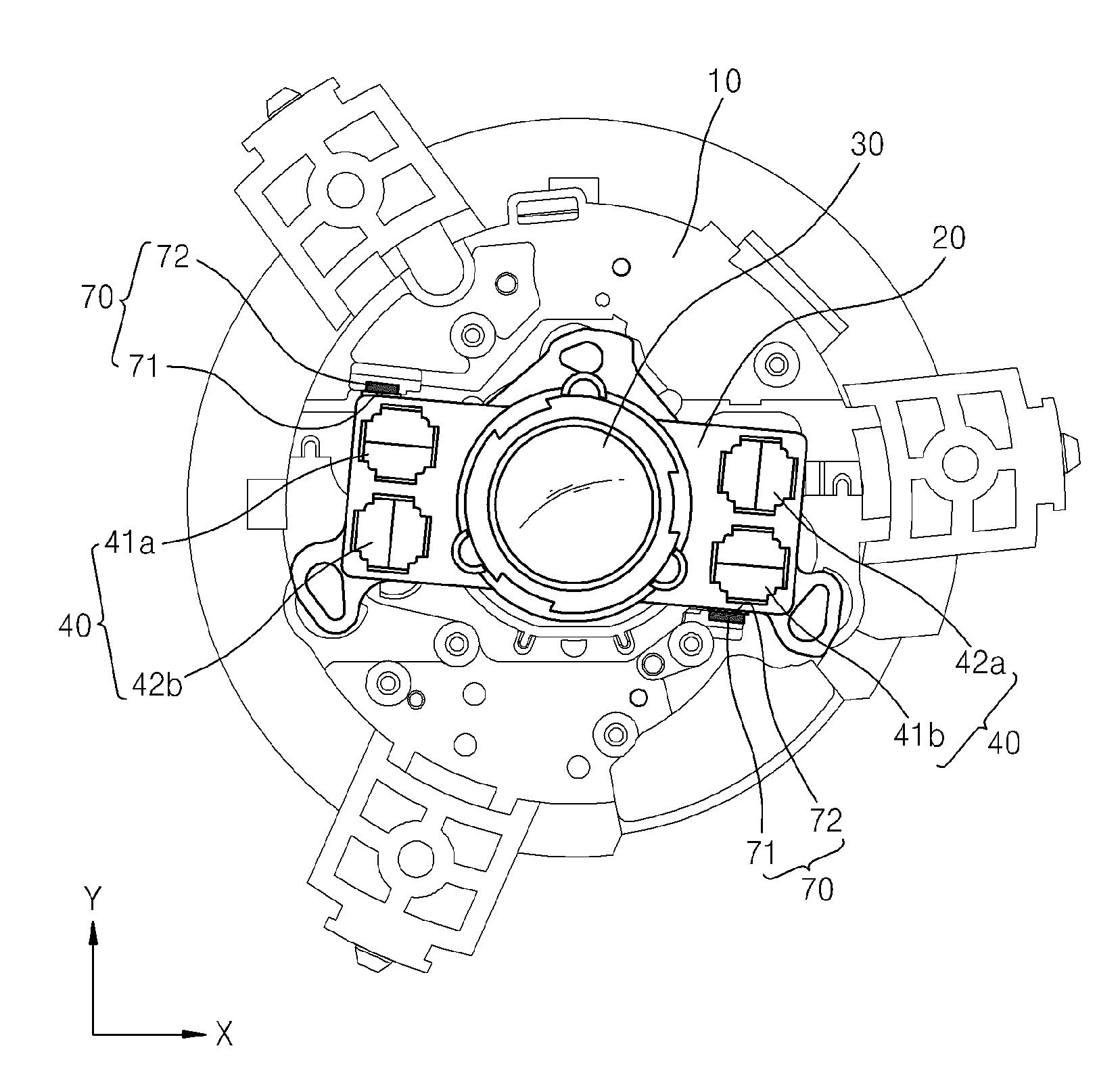
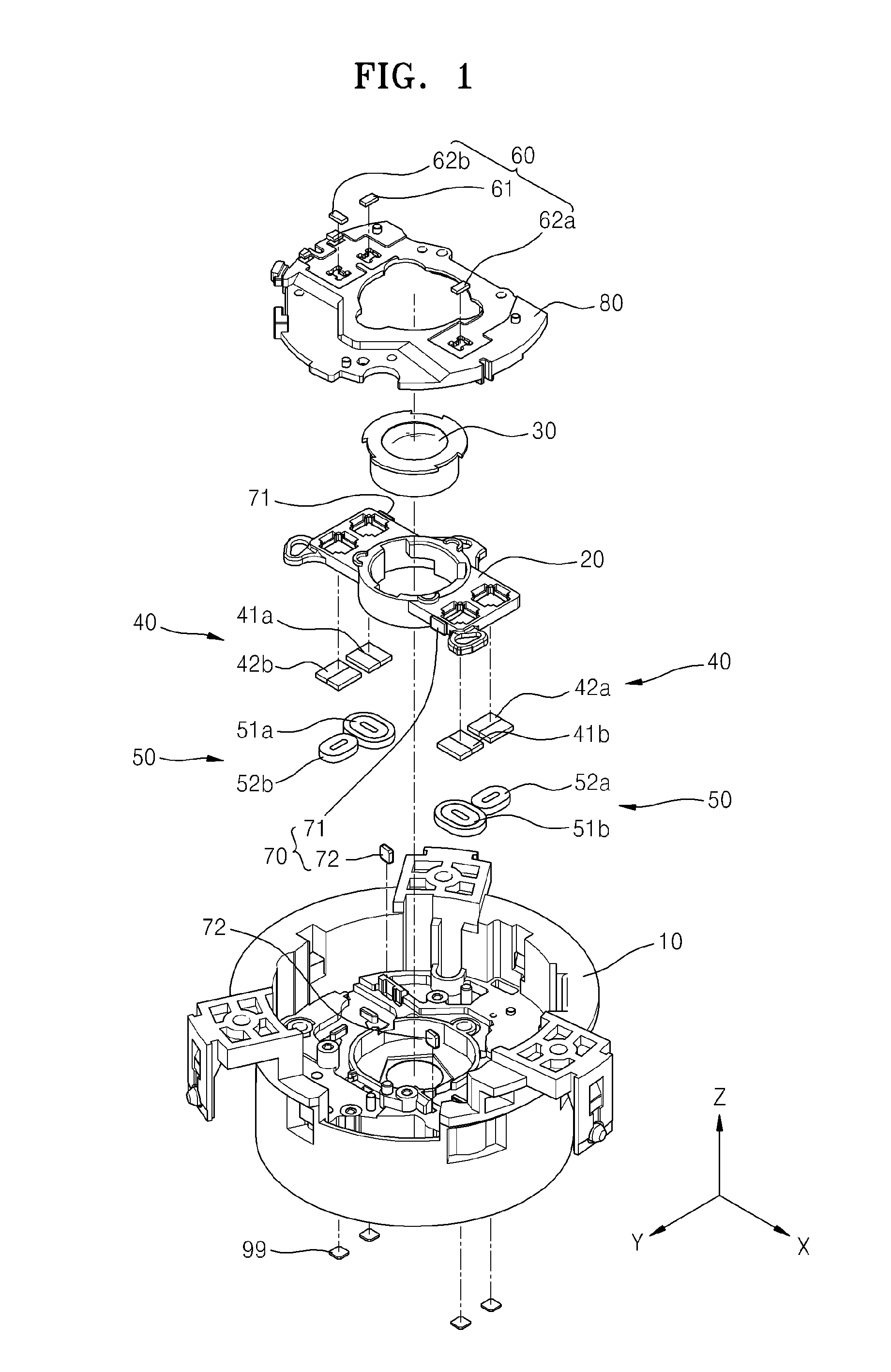
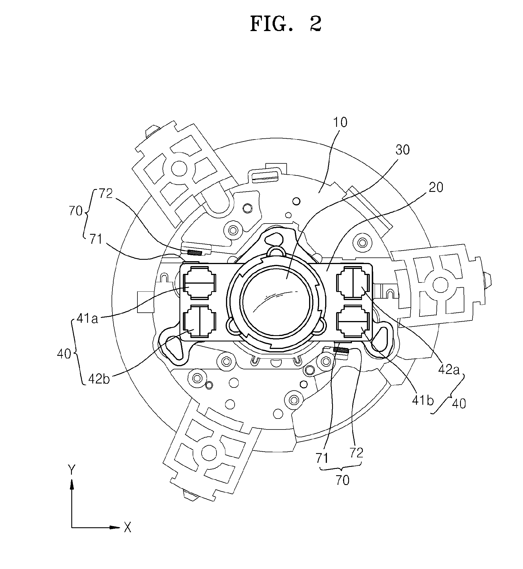
[0037]FIG. 1 is an exploded perspective view of elements of an apparatus for adjusting a position of an optical element, according to an embodiment of the invention, and FIG. 2 is a plan view of the apparatus for adjusting a position of an optical element illustrated in FIG. 1.

[0038]The apparatus for adjusting a position of an optical element illustrated in FIGS. 1 and 2 includes a support 10, a movement unit 20 that is movable relative to the support 10, magnet units 40 disposed on the support 10 or the movement unit 20, coil units 50 that generate a magnetic force that act on respective ones of the magnetic units 40, a sensor unit 60 that generates a signal according to a relative position of the movement unit 20 with respect to the magnetic units 40 and ...


PUM


Abstract

An apparatus for adjusting a position of an optical element is disclosed. The apparatus includes: a support; a movement unit for supporting an optical element and being movable relative to the support; a magnet unit; a coil unit for generating a magnetic force for moving the movement unit when an electrical signal is applied; a sensor unit disposed in a position corresponding to the magnet unit for detecting a relative position of the movement unit with respect to the support; a locking unit for limiting or allowing movement of the movement unit; and a controlling unit connected to the coil unit for controlling the coil unit and determining whether the movement unit is in a state where movement of the movement unit is limited by the locking unit based on a signal output from the sensor unit.

Description

CROSS-REFERENCE TO RELATED PATENT APPLICATIONS[0001]This application claims the priority benefit of Korean Patent Application No. 10-2011-0022456, filed on Mar. 14, 2011 in the Korean Intellectual Property Office, which is incorporated herein in its entirety by reference.BACKGROUND OF THE INVENTION[0002]1. Field of the Invention[0003]One or more aspects of the invention relate to a method and an apparatus for adjusting a position of an optical element, and, more particularly, to a method and an apparatus for adjusting a position of an optical element, whereby movement of a movement unit is limited so that the position of the optical element may be stably maintained.[0004]2. Description of the Related Art[0005]Shake correction apparatuses used in a camera perform a function of preventing a clearness of an image from being lowered due to a user's hand tremble. Shake correction apparatuses include a power operated driving device that changes a position of an optical element such as a l...

Claims


Application Information

Patent Timeline
Patent Type & Authority Applications(United States)
IPC IPC(8): G02B27/64
CPCG02B27/646G03B5/02H04N5/23258G02B27/64G03B2205/0007G03B2205/0069H04N5/23287H04N23/6812H04N23/687G03B17/02
Inventor HWANG, YOUNG-JAELEE, JIN-GIBYON, KWANG-SEOK
Owner SAMSUNG ELECTRONICS CO LTD
Why Eureka
Try Eureka