Liquid ejecting apparatus, and control method for liquid ejecting apparatus

a technology of liquid ejecting apparatus and control method, which is applied in the direction of printing, other printing apparatus, etc., can solve the problems of increasing power consumption of printers, affecting the ejection of liquid droplets, so as to minimize power consumption and reduce power consumption.

Active Publication Date: 2016-01-05
SEIKO EPSON CORP
View PDF3 Cites 0 Cited by
  • Summary
  • Abstract
  • Description
  • Claims
  • Application Information

AI Technical Summary

Benefits of technology

[0012]Embodiments of the invention relate to a liquid ejecting apparatus capable of minimizing power consumption, and a control method for controlling the liquid ejecting apparatus or for minimizing or reducing power consumption in a liquid ejecting apparatus.
[0014]In one example, because the second reference potential which is used as a reference of a potential change in the second driving signal is set to be lower than the first reference potential which is used as a reference of a potential change in the first driving signal, a general potential of the second driving signal is reduced. Thus, it is possible to reduce power consumption in a period or during a time when the liquid is not ejected onto a landing target. As a result, it is possible to contribute to the power consumption saving of the liquid ejecting apparatus. In other words, it is possible to reduce the power consumed in the liquid ejecting apparatus. In addition, since the second reference potential, which is not 0 or is greater than 0, is applied to each piezoelectric element in the period when liquid is not ejected onto the landing target, it is possible to perform a smooth transition from a liquid ejection suspension state to a liquid ejection operation as compared with a case where a driving signal is not applied (e.g., an applied potential is 0). The transition to a first reference potential from a potential that is higher than 0 can be achieved more smoothly than a transition from an applied potential of 0 to the first reference potential.
[0018]According to one configuration, since the driving pulse includes the first waveform part which is changed from the second reference potential to a potential higher than the second reference potential, and the second waveform part which is changed from the higher potential to the second reference potential, the driving pulse has a waveform with a shape protruding upwardly (a higher potential side than the second reference potential) so as to be changed to a potential higher than the reference potential. Thus the second reference potential can be set to the lowest value in a range which can be set in terms of a specification or design of a driving signal generator. For this reason, it is possible to further reduce power consumption. The second reference potential could also be set to the lowest potential that sill allows a smooth transition to the printing operation.

Problems solved by technology

However, if the solvent component has evaporated, there is a concern that the liquid near the nozzles may thicken and that the ejection of the liquid droplets may thus be hindered.
As a result, the power consumption of the printer increases.
In contrast, if the driving signal is not applied to the pressure generator in the non-recording region (an applied potential is 0), a non-printing slight vibration is not performed and it is hard to prevent thickening of the ink.
Therefore, there is a problem in that the transition from a state in which the applied potential is 0 to a state of execution and restarting of the printing (execution of ejection of ink) is not smoothly performed.
In addition, these problems occur not only the ink jet recording apparatuses in which recording heads which eject ink but also other liquid ejecting apparatuses which eject a liquid from nozzles by causing a pressure fluctuation in a liquid in a pressure chamber.

Method used


Image

  • Liquid ejecting apparatus, and control method for liquid ejecting apparatus
  • Liquid ejecting apparatus, and control method for liquid ejecting apparatus
  • Liquid ejecting apparatus, and control method for liquid ejecting apparatus

Examples


Embodiment Construction

[0027]Hereinafter, an embodiment of the invention will be described with reference to the accompanying drawings. In addition, the embodiments described below are described with reference to various examples, but the scope of the invention is not limited to such unless the effect of limiting the invention is particularly stated in the following description. Further, in the following, the liquid ejecting apparatus according to embodiments of the invention will be described by exemplifying an ink jet recording apparatus (hereinafter, a printer).

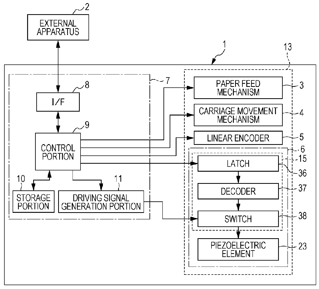
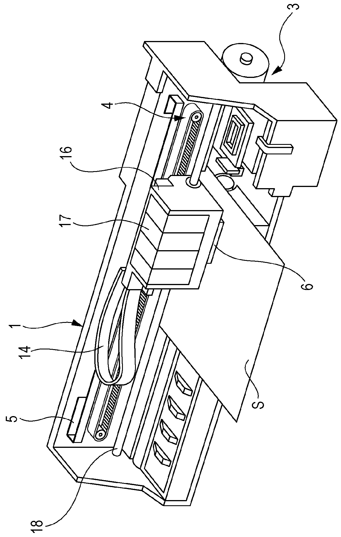
[0028]FIG. 1 is a block diagram illustrating an example of an electrical configuration of a printer 1, and FIG. 2 is a perspective view illustrating an example of an internal configuration of the printer 1. An external apparatus 2 may be an electronic apparatus such as a computer, a digital camera, or a portable information terminal. The external apparatus 2 is electrically connected to the printer 1 in a wired or wireless manner, and transmits ...


PUM


Abstract

In a recording suspension period when a recording head is accelerated or decelerated in a non-recording region on a recording medium, or stops moving in the course of performing a printing process (printing job), a second driving signal is generated from a driving signal generation portion. Second vibration driving pulses of the second driving signal are applied to all piezoelectric elements, so that a vibration operation is performed without ejecting the liquid. Since a second reference potential of the second driving signal is set to be lower than a first reference potential of a first driving signal generated in a recording period as much as possible, a general potential (driving voltage) of the second driving signal is reduced, and reduce power consumption in the recording suspension period is reduced. As a result, it is possible to contribute to the power consumption saving of a printer.

Description

[0001]The present application claims priority to Japanese Patent Application No. 2013-157319 filed on Jul. 30, 2013 and No. 2014-132351 filed on Jun. 27, 2014, which are hereby incorporated by reference in their entirety.BACKGROUND[0002]1. Technical Field[0003]Embodiments of the present invention relate to a liquid ejecting apparatus such as an ink jet recording apparatus, and a control method for controlling the liquid ejecting apparatus. More particularly, embodiments of the invention relate to a liquid ejecting apparatus which applies a driving signal to a piezoelectric element so as to drive the piezoelectric element, thereby ejecting a liquid from nozzles, and a control method for controlling the liquid ejecting apparatus.[0004]2. Related Art[0005]A liquid ejecting apparatus is an apparatus that includes a liquid ejecting head and that ejects various liquids from the liquid ejecting head. Examples of the liquid ejecting apparatus include, for example, an image recording apparat...

Claims


Application Information

Patent Timeline
Patent Type & Authority Patents(United States)
IPC IPC(8): B41J29/38B41J2/45B41J2/045
CPCB41J2/04541B41J2/0452B41J2/04581B41J2/04588
Inventor FUKUDA, SHUNYA
Owner SEIKO EPSON CORP
Why Eureka
Try Eureka