Light guide plate, and backlight unit and mobile device including the same

a technology of backlight unit and light guide plate, which is applied in the direction of optical light guide, optics, instruments, etc., can solve the problems of increasing power consumption, and achieve the effect of reducing or minimizing power consumption

Active Publication Date: 2018-01-23
LG ELECTRONICS INC
View PDF16 Cites 0 Cited by
  • Summary
  • Abstract
  • Description
  • Claims
  • Application Information

AI Technical Summary

Benefits of technology

[0015]Another aspect of the present invention is directed to provide a mobile device in which power consumption is reduced or minimized when displaying a fast execution screen.

Problems solved by technology

For this reason, since the related art mobile device may not control a partial luminance of the backlight unit, all the LEDs of the backlight unit are driven when executing a partial display function, causing an increase in power consumption.

Method used


Image

  • Light guide plate, and backlight unit and mobile device including the same
  • Light guide plate, and backlight unit and mobile device including the same
  • Light guide plate, and backlight unit and mobile device including the same

Examples


first embodiment

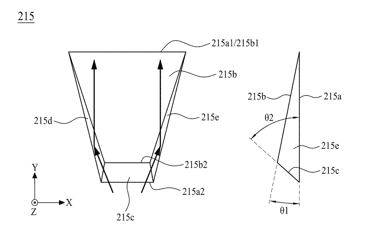
[0081]The light guide plate 210 according to the present invention may include a body 211, an upper optical pattern 213, and a lower optical pattern 215.

[0082]The body 210 may be formed in a plate form having a short side and a long side. One side of the short side of the body 211 may be defined as the light incident part 210a, and the other side of the short side of the body 211 may be defined as a light non-incident part 210b. The body 211 may be formed of one material selected from among poly methyl methacrylate, polyethersulfone, polycarbonate, acrylonitrile styrene, polyesterimide, polymethylpentene, polystyrene, polyamide, and silicon.

[0083]The upper optical pattern 213 according to an embodiment may be provided on a top of the body 211 to have a constant interval and may include a curved surface. The upper optical pattern 213 may control a path of light incident on the light incident part 210a of the body 211. The upper optical pattern 213 may enhance linearity of the light i...

second embodiment

[0090] the light source unit 220 may include first to third light emitting array groups arranged along the first direction X. For example, the first light emitting array group may include a plurality of LED packages which are disposed on one side of the short side of the light guide plate 210, the second light emitting array group may include a plurality of LED packages which are disposed in a middle portion of the short side of the light guide plate 210, and the third light emitting array group may include a plurality of LED packages which are disposed on the other side of the short side of the light guide plate 210. Here, the first and third light emitting array groups may include a same number of LED packages 223, and the second light emitting array group may include LED packages 223 equal to the total number of the LED packages 223 included in the first and third light emitting array groups.

third embodiment

[0091] the light source unit 220 may include first to fifth light emitting array groups arranged along the first direction X. For example, the first light emitting array group may include a plurality of LED packages which are disposed on one side of the short side of the light guide plate 210, the second light emitting array group may include a plurality of LED packages which are disposed in a middle portion of the short side of the light guide plate 210, and the third light emitting array group may include a plurality of LED packages which are disposed on the other side of the short side of the light guide plate 210. Also, the fourth light emitting array group may include a plurality of LED packages which are disposed on the other side of the short side of the light guide plate 210, and the fifth light emitting array group may include a plurality of LED packages which are disposed between the second and fourth light emitting array groups. Here, the first, second and fourth light em...


PUM

PropertyMeasurementUnit
angleaaaaaaaaaa
angleaaaaaaaaaa
heightaaaaaaaaaa

Abstract

A light guide plate in accordance with various embodiments comprises: a body having a light incident part at a first side surface of the body; an upper optical pattern at a top side of the body; and a lower optical pattern at a bottom side of the body, wherein the lower optical pattern is an embossed pattern protruding from the bottom side of the body and having a trapezoid shape, wherein a first end of the trapezoid shape has a first width and a second end of the trapezoid shape has a second width, wherein the first end is closer to the light incident part than the second end, and wherein the first width is narrower than the second width.

Description

CROSS-REFERENCE TO RELATED APPLICATIONS[0001]This application claims the benefit of Korean Patent Application No. 10-2015-0107390 filed on Jul. 29, 2015, which is hereby incorporated by reference as if fully set forth herein.BACKGROUND[0002]Field of the Invention[0003]The present invention relates to a light guide plate, and a backlight unit and an electronic device including the same.[0004]Discussion of the Related Art[0005]Generally, liquid crystal display (LCD) devices are being widely used as display screens of various products such as televisions (TVs), notebook computers, monitors, etc., in addition to mobile devices such as mobile communication terminals, electronic notebooks, e-books, portable multimedia players (PMPs), navigation devices, ultra-mobile personal computers (UMPCs), mobile phones, smartphones, tablet personal computers (PCs), watch phones, etc.[0006]Recently, mobile devices have a partial display function for quickly executing a message function, a call functio...

Claims


Application Information

Patent Timeline
Patent Type & Authority Patents(United States)
IPC IPC(8): F21V8/00G02F1/1335
CPCG02B6/0036G02B6/0016G02B6/0038G02B6/0061G02F2001/133607G02B6/0073G02F1/133603G02F1/133606G02B6/0058G02B6/0035G02B6/0043G02F1/133607
Inventor SONG, YOUNG KIPARK, MYUNGJOON
Owner LG ELECTRONICS INC
Why Eureka
Try Eureka