Method and apparatus for thermocouple installation or replacement in a substrate support

a technology of substrate support and thermocouple, which is applied in the direction of metal working apparatus, manufacturing tools, coatings, etc., can solve the problems of difficult access to embedded thermocouples, large time-consuming and labor-intensive removal of materials, and failure of thermocouples

Inactive Publication Date: 2012-09-27
APPLIED MATERIALS INC
View PDF16 Cites 220 Cited by
  • Summary
  • Abstract
  • Description
  • Claims
  • Application Information

AI Technical Summary

Benefits of technology

[0012]In another embodiment, a method for installing one or more temperature sensors in a substrate support suitable for use in a vacuum chamber is provided. The method comprises cleaning the substrate support, drilling a blind hole in a bottom surface of the substrate support, placing a probe of a temperature sensor in the opening, and installing a cover over the temperature sensor, wherein the cover seals the temperature sensor in a volume that is isolated from the environment exterior of the cover and the volume is in fluid communication with an annulus of a support stem coupled to the body.
[0013]In another embodiment, a process kit for use in a vacuum chamber is provided. The process kit comprises one or more temperature probes, one or more housings adapted to contain at least a portion of one of the one or more temperature probes, one or more conduits. Each of the one or more conduits comprise a fitting at a first end thereof, and a fitting at a second end thereof for coupling to one of the one or more housings, and one or more straps for coupling to the one or more conduits.

Problems solved by technology

However, thermocouples are subject to failure and require replacement during predetermined preventative maintenance operations.
The embedded thermocouples are difficult to access as portions of the body of the substrate support must be removed by drilling or gouging to expose the thermocouple.
The removal of material takes substantial time which causes increased downtime of the CVD chamber.
Replacement is also difficult as the wiring and mounting of a new thermocouple takes substantial time.
All of these operations cause considerable downtime of the CVD chamber when one or more of the thermocouples need to be replaced.
Substrate supports utilized in other types of vacuum chambers have the same problem.

Method used


Image

  • Method and apparatus for thermocouple installation or replacement in a substrate support
  • Method and apparatus for thermocouple installation or replacement in a substrate support
  • Method and apparatus for thermocouple installation or replacement in a substrate support

Examples


Embodiment Construction

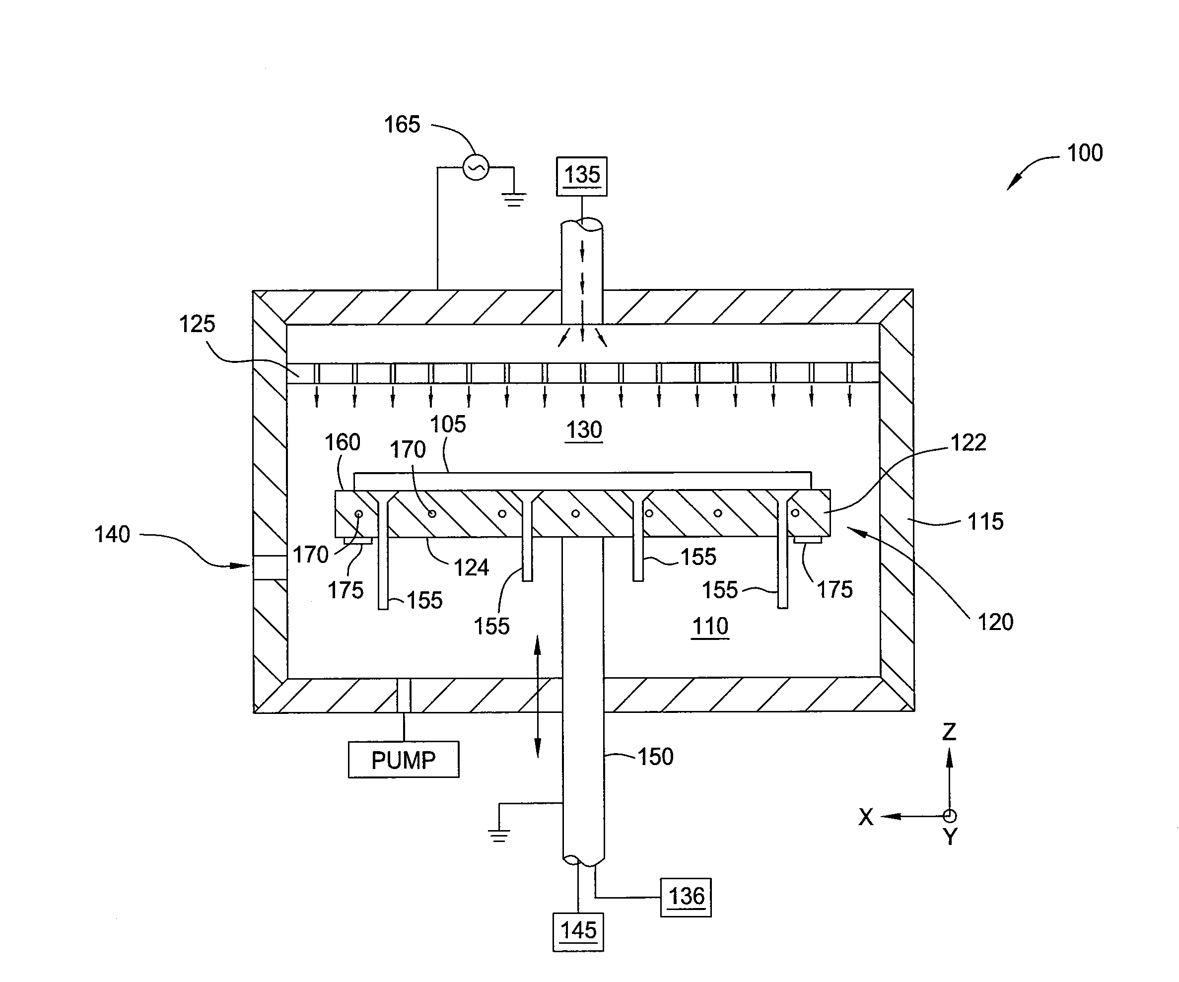
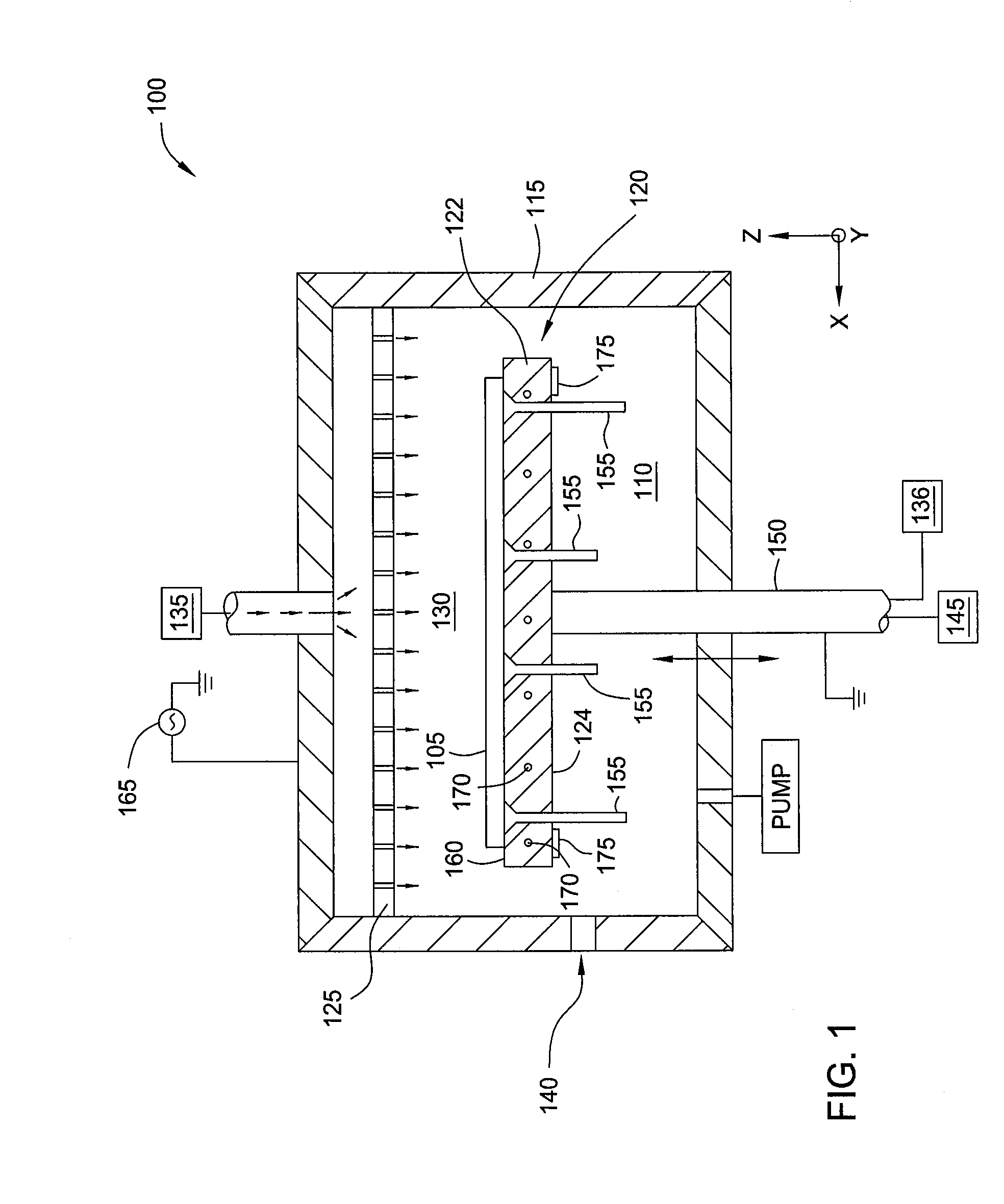
[0021]FIG. 1 is a side cross-sectional view of one embodiment of a vacuum chamber 100 suitable for processing substrates, such as wafers or flat media, in the manufacture of flat panel displays, solar panels, light emitting diodes (LEDs) or other electronic devices. For the sake of brevity and not by way of limitation, the vacuum chamber 100 is illustrated as a plasma enhanced chemical vapor deposition (PECVD) chamber. Embodiments described herein may also be utilized in vacuum chambers configured for other processes, such as physical vapor deposition (PVD) processes, etch processes, or other vacuum process on a substrate or multiple substrates. In addition, the vacuum chamber 100 may be a stand-alone chamber, an in-line chamber, a cluster tool chamber, or some combination or variation thereof.

[0022]The vacuum chamber 100 is configured to receive a substrate 105 within an evacuable processing volume 110 defined inside walls of the vacuum chamber 100. The vacuum chamber 100 includes ...


PUM

PropertyMeasurementUnit
volumeaaaaaaaaaa
interior volumeaaaaaaaaaa
coupling interfaceaaaaaaaaaa

Abstract

An apparatus and method for one or more externally mounted temperature sensors in a substrate support utilized in a chemical vapor deposition (CVD) chamber is provided. In one embodiment, a substrate support for a vacuum chamber is provided. The substrate support comprises a body having a substrate receiving surface and an opposing bottom surface, a support stem coupled to and extending away from the bottom surface, one or more thermal control devices embedded within the body, at least one temperature sensor interfaced with the bottom surface of the body, and a removable hermitic enclosure fastened to the second side of the body and covering the at least one temperature sensor.

Description

CROSS-REFERENCE TO RELATED APPLICATIONS[0001]This application claims benefit of U.S. Provisional Patent Application Ser. No. 61 / 467,928 (Attorney Docket No. 11673USAL), filed Mar. 25, 2011, which is hereby incorporated by reference herein.BACKGROUND OF THE INVENTION[0002]1. Field of the Invention[0003]Embodiments of the present invention generally relate to substrate supports having thermocouples for use in vacuum processing chambers, such as chemical vapor deposition (CVD) chambers, physical vapor deposition (PVD) chambers, etch chambers and plasma treatment chambers, among others.[0004]2. Description of the Related Art[0005]CVD is a process whereby a gas is introduced into a vacuum chamber to deposit a material layer onto a substrate. The gas may be dissociated prior to deposition on the substrate by dissociating the gas thermally and / or igniting the gas into a plasma (i.e., a PECVD process). There are many applications for utilizing a CVD or a PECVD process such as to deposit lay...

Claims


Application Information

Patent Timeline
Patent Type & Authority Applications(United States)
IPC IPC(8): B44C1/22B05C11/00B05C13/00B23P19/00
CPCY10T29/53C23C16/4586
Inventor DIELMANN, JOERGRUEDIGER, REINER
Owner APPLIED MATERIALS INC
Why Eureka
Try Eureka