Non-Pneumatic Irrigation System Tower Support Wheel

a technology of non-pneumatic irrigation system and support wheel, which is applied in the direction of hubs, non-skid devices, transportation and packaging, etc., can solve the problems of destroying the crops in its path, causing the wheel to be quite large and heavy, and almost certainly to be quite heavy

Inactive Publication Date: 2012-09-27
WERNER MICHAEL
View PDF3 Cites 23 Cited by
  • Summary
  • Abstract
  • Description
  • Claims
  • Application Information

AI Technical Summary

Problems solved by technology

These wheels tend to be quite large and heavy.
A tractor can be used to transport the wheel but driving the tractor across the field of growing crops will almost certainly destroy the crops that are in its path.
A wheel can often be rolled to and from a site but it may require two people and consume a good number of the hours in a day.
As can be appreciated, the ground beneath the tires often becomes muddy.
The tread of the tire can fill with mud and thereby lose its ability to gain traction over the ground.
Finally, pneumatic rubber tires tend to form deep ruts in the muddy ground over which they travel.
When tractors drive over these ruts, such as during or after harvest especially after the ground has hardened, damage to the tractor in the form of cracked axles and / or flat tires can result.

Method used


Image

  • Non-Pneumatic Irrigation System Tower Support Wheel
  • Non-Pneumatic Irrigation System Tower Support Wheel
  • Non-Pneumatic Irrigation System Tower Support Wheel

Examples


Embodiment Construction

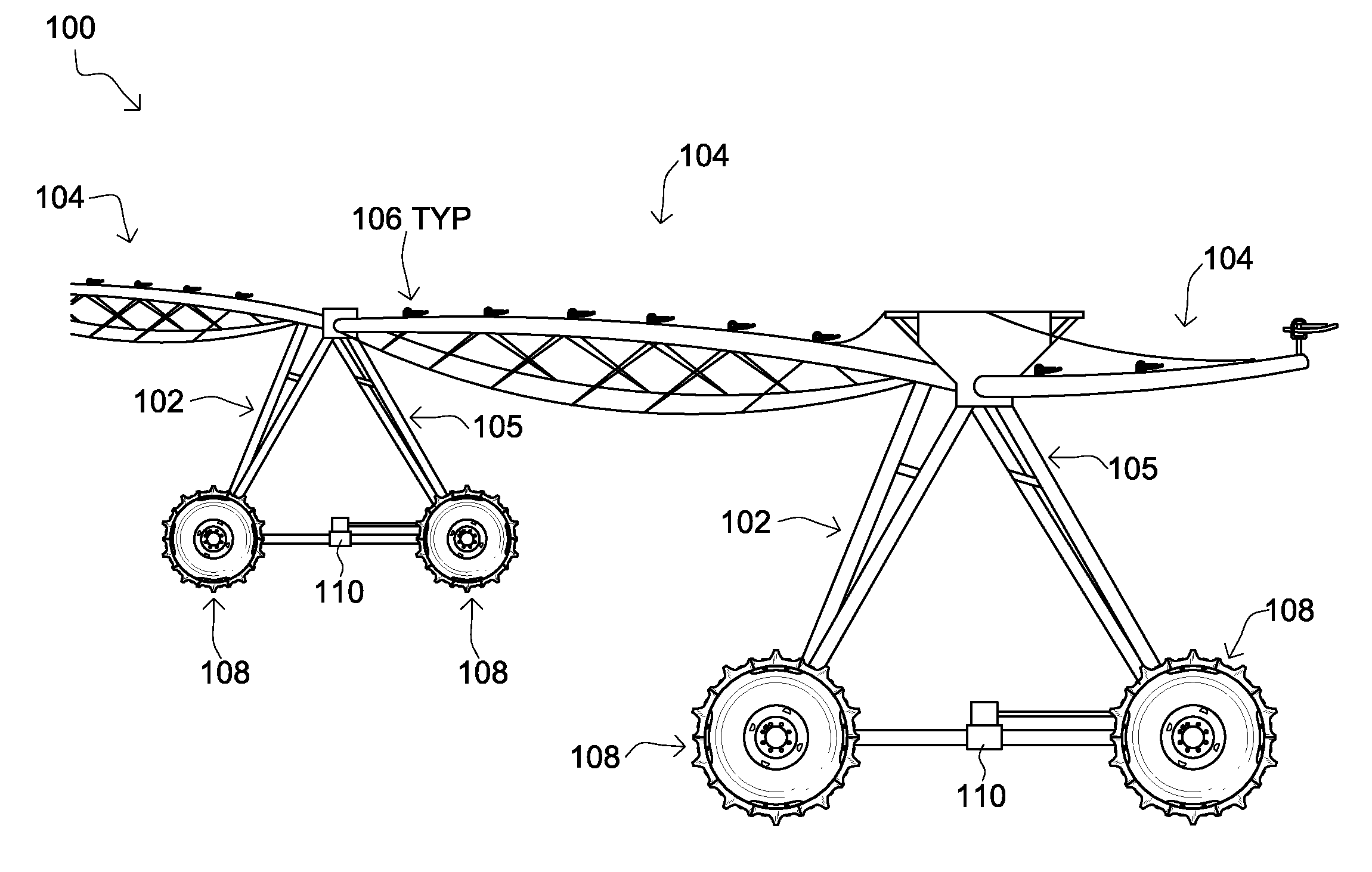
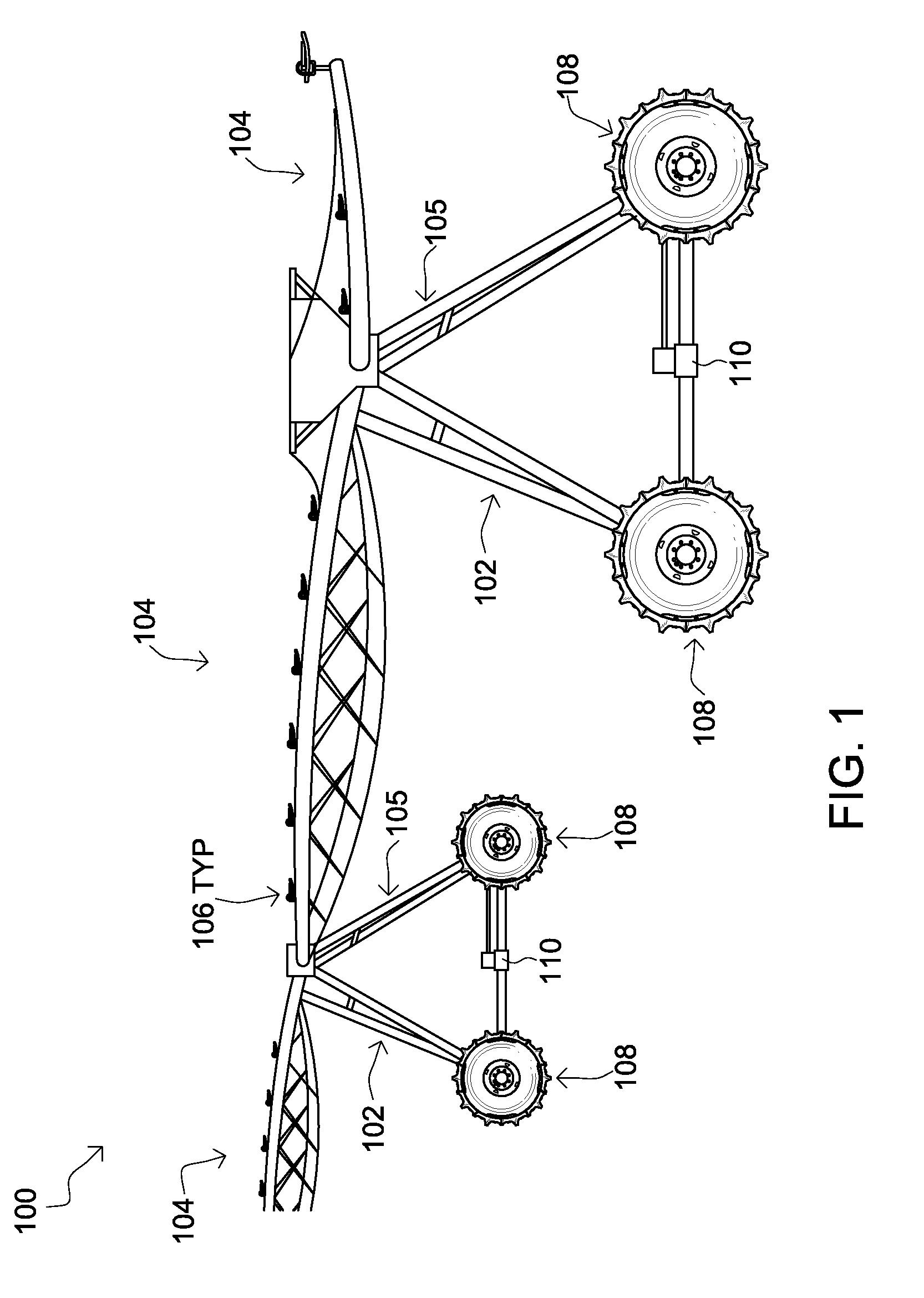
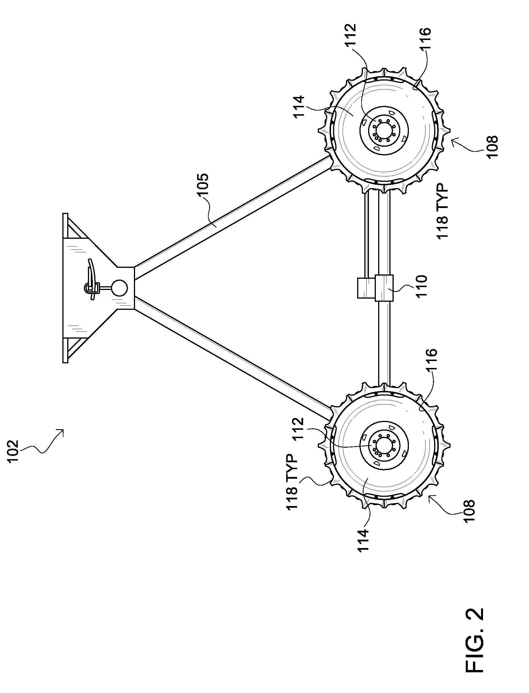
[0012]Embodiments of the present invention comprise a wheel assembly for use on a tower of an irrigation system. The wheel assembly comprises a generally cylindrical wheel having a hub, one or more spokes and a rim to which a plurality of non-pneumatic tire sections are mounted to encircle and effectively cover the circumferential outwardly facing surface of the rim. The tire segments are typically solid and comprised of a resilient polymeric material such as polyurethane.

[0013]The foregoing design offers several advantages over prior art wheel assemblies that incorporate a pneumatic tire. Significantly, there is no traditional tire to be punctured reducing the risk that the wheel assembly will become damaged necessitating repair and replacement of a damaged tire. Further, in some embodiments, if a tire section becomes damaged, it can be individually removed and replaced. As is intuitively obvious, it is much easier to transport individual tire sections to tower in a planted field t...


PUM

PropertyMeasurementUnit
diameteraaaaaaaaaa
diameteraaaaaaaaaa
diameteraaaaaaaaaa

Abstract

The present invention comprises a wheel assembly for use on a tower of an irrigation system. The wheel assembly comprises a generally cylindrical wheel having a hub, one or more spokes and a rim to which a plurality of non-pneumatic tire sections are mounted to encircle and effectively cover the circumferential outwardly facing surface of the rim. The tire segments are typically solid and comprised of a resilient polymeric material such as polyurethane.

Description

FIELD OF THE INVENTION[0001]The present invention pertains generally to wheels for irrigation systems.BACKGROUND[0002]Irrigation systems are used to irrigate farm land that is located in regions that do not regularly and reliably receive sufficient rainfall to dispense with supplemental watering. Typical irrigation systems comprise a series of spaced support towers that are connected at their top ends by booms or boom assemblies. The boom assemblies, which can extend 180 feet or so in length, carry the irrigation water to sprinkler heads that are distributed along their lengths. Between two and twenty booms (or spans) can be coupled together to irrigate a swath of land to nearly three quarter of a mile long. The entire structure travels either circumferentially about a pivot or linearly to irrigate large tracts. Accordingly, each tower includes two or more wheels to impart mobility and provide for the propulsion of the structure across the associated tract.[0003]The majority of curr...

Claims


Application Information

Patent Timeline
Patent Type & Authority Applications(United States)
IPC IPC(8): A01G25/06B23P6/00B60C11/03B60C25/00B60B21/06B60B27/00
CPCB60C11/0311B60C2200/08B60C2011/0016A01G25/092Y10T29/49481B60B27/065B60C7/08B60C7/26B60B21/06
Inventor WERNER, MICHAEL
Owner WERNER MICHAEL
Why Eureka
Try Eureka