
Energy consumption management

Active Publication Date: 2012-09-27
REACTIVE TECH
View PDF6 Cites 90 Cited by
  • Summary
  • Abstract
  • Description
  • Claims
  • Application Information

AI Technical Summary

Benefits of technology

[0012]sending one or more requests, for receipt at the electric devices of the selected groups, to control electrical energy consumption and / or provision by the electric devices, thereby reducing a net consumption of electrical energy in said geographical area, during a respective associated time interval.
[0059]In some embodiments, the electric devices whose profile information is stored in the device database are associated with different user accounts, and the central node comprises a user interface for a said user to access a said account and to alter information stored in the device database. This feature allows users to amend desired operating characteristics of the electric devices they own in real time, so as to prevent the system restricting use of devices inconveniently.

Problems solved by technology

Since it is expensive to store electricity in large quantities, it is usually generated when it is required, which can place a burden on power generators as they attempt to meet demand at peak times. Furthermore, in recent years, a greater proportion of electricity is being generated by intermittent renewable energy forms, such as solar or wind power, whose ability to generate power is dependent on environmental conditions that are difficult to predict and are beyond the control of the operator of the power generator.
There may also be considerable variation in demand for electrical energy between different geographical areas; it may be difficult to supply the required amount of electric energy to areas of high demand, known as “hot spots”, resulting in potential power cuts in these areas, and / or an inefficient distribution of network resources.
However, this places considerable burden on the user performing the monitoring.
However, this approach can cause considerable inconvenience to users, who may be unable to use their devices for extended periods of time.

Method used


Image

  • Energy consumption management
  • Energy consumption management
  • Energy consumption management

Examples


Embodiment Construction

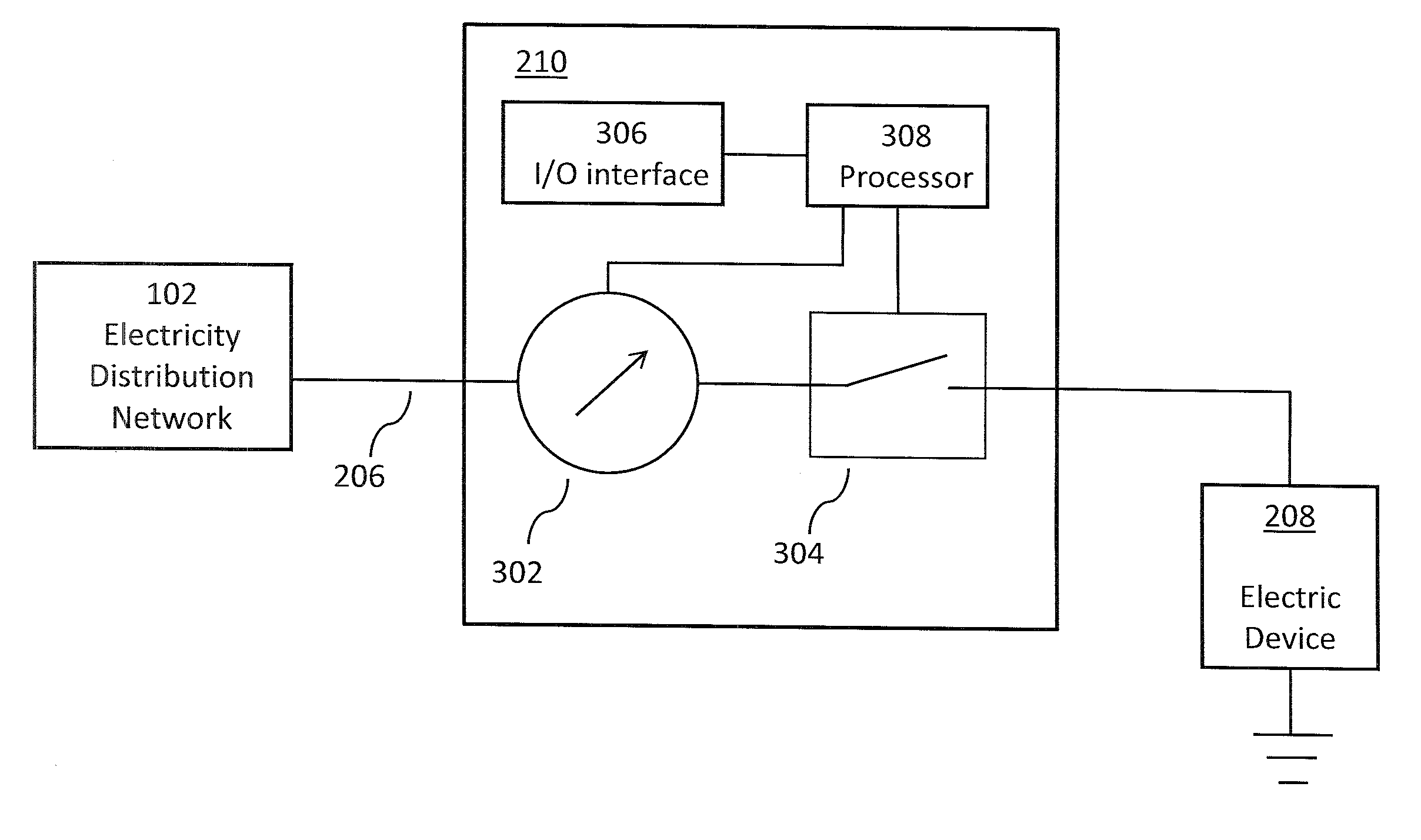
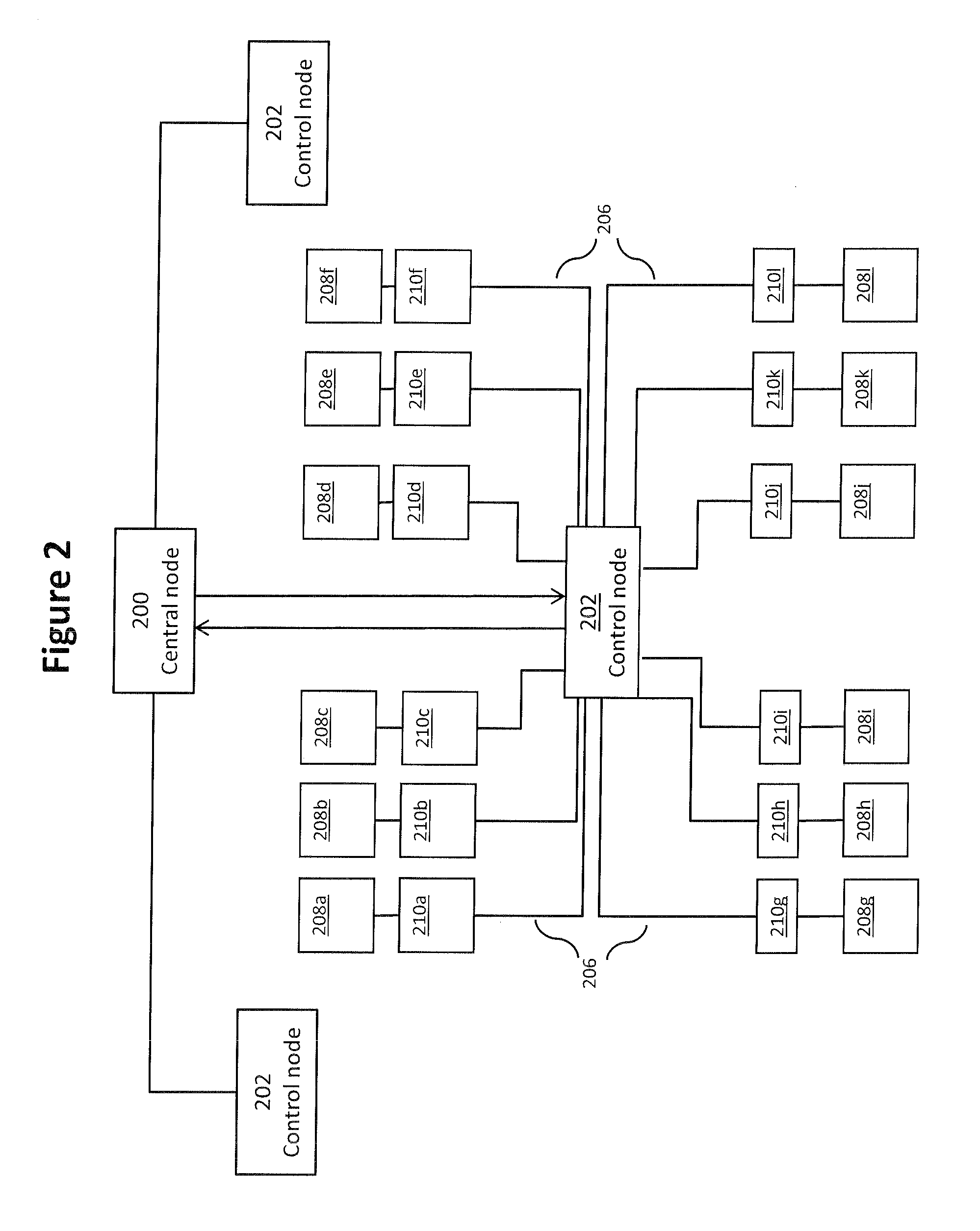
[0078]FIG. 2 illustrates an electricity distribution network in which an embodiment of the present invention may be implemented. The network comprises a central node 200 connected to one or more control nodes 202 that each cover a geographical area, for example a country, region, state, postal-code, or electricity market region, or any other area comprising multiple user premises (i.e. multiple residences or workplaces). Each of the control nodes 202 are connected by power lines 206, via substations and / or distribution feeders, to energy consumption / provision devices 208a to 208l, hereinafter referred to as electric devices 208. Each of the electric devices 208a to 208l consumes and / or provides electric energy. Examples of electric devices 208 consuming electric energy include domestic appliances such as electric water heaters, air-conditioning units and washing machines, as well as industrial devices, such as factory machinery. Examples of providers of electric energy include gener...


PUM


Abstract

Methods, systems, and devices for controlling electrical energy consumption in an electricity distribution network, so as to reduce net energy consumption in a given area during a given time period, are described. In particular, a method of controlling electrical energy consumption within an electricity distribution network is described. The method comprises maintaining a database of information about electric devices, and identifying a time period during which consumption of electrical energy is to be controlled. The method further comprises selecting, based on device profile information stored in the database, groups of electric devices, and associating one or more time intervals with each of the selected groups. Requests are sent to the electric devices of the selected groups to control electrical energy consumption and / or provision by the electric devices. This enables a reduction in net consumption of electrical energy during a respective time interval.

Description

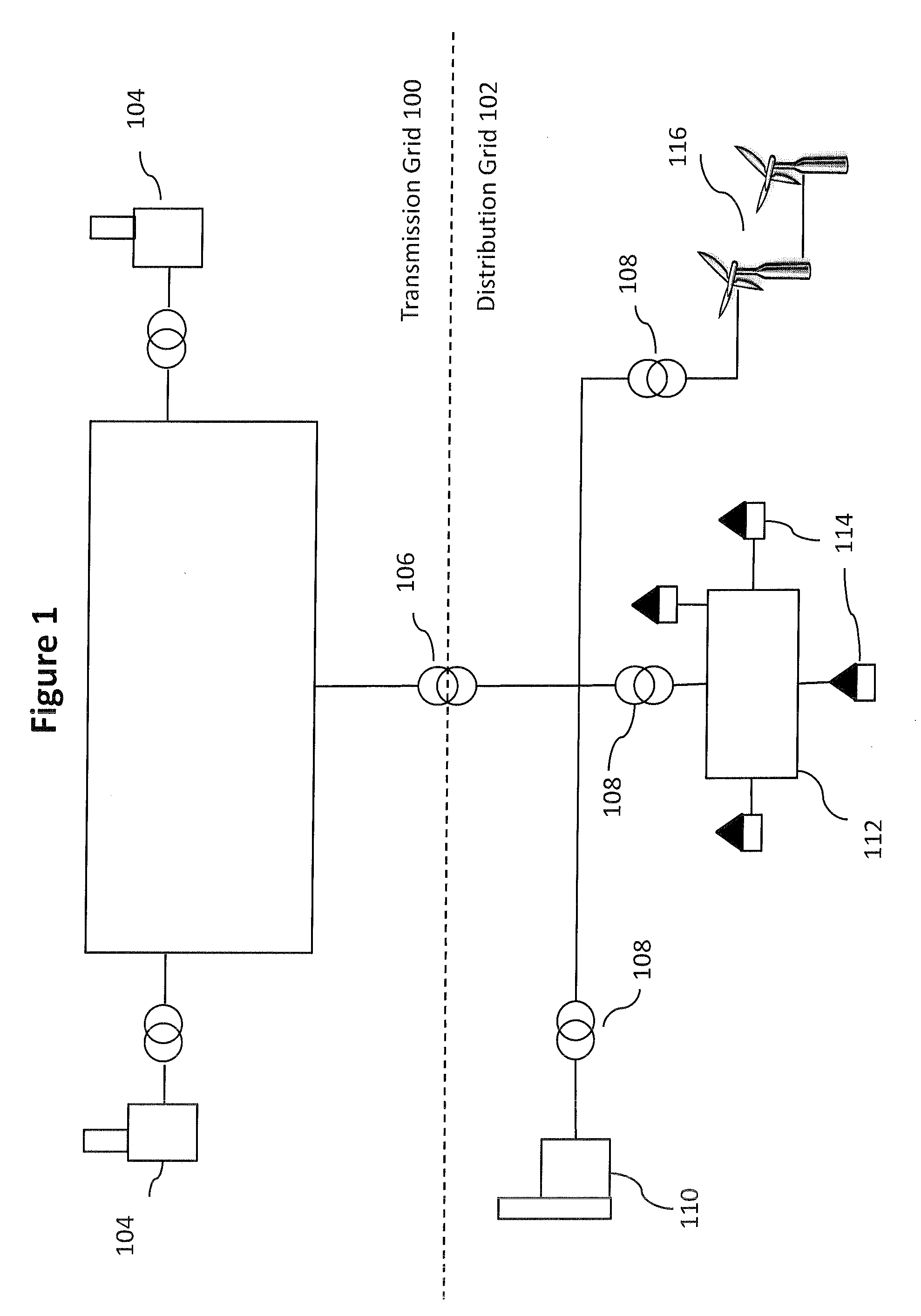
CROSS-REFERENCE TO RELATED APPLICATIONS[0001]The present application claims priority under 35 USC 119 of UK Patent Application GB 1104986.3 filed Mar. 24, 2011, the entire disclosure of each of which is incorporated herein by reference.FIELD OF THE INVENTION[0002]The present invention relates to management of energy consumption in an electricity distribution network. In particular, but not exclusively, it relates to management of energy consumption and provision by groups of electric devices connected to the network.BACKGROUND OF THE INVENTION[0003]Supply of electricity from power generators such as power stations, to consumers, such as domestic households and businesses, typically takes place via an electricity distribution network. FIG. 1 shows an exemplary distribution network comprising a transmission grid 100 and a distribution grid 102. The transmission grid is connected to generating plants 104, which may be nuclear plants or gas-fired plants, for example, from which it trans...

Claims


Application Information

Patent Timeline
IPC IPC(8): G06F1/32
CPCG06Q10/06G06Q50/06H02J3/14H02J4/00Y04S20/222Y02B70/3266Y04S20/242Y02B70/3225G06Q10/06312Y02P90/82H02J2310/12H02J2310/14Y02B70/30
Inventor BORRETT, MARCHUOMO, HEIKKI
Owner REACTIVE TECH
Learn More