
Method and apparatus for controlling fluid flow in an autonomous valve using a sticky switch

Active Publication Date: 2012-10-11
HALLIBURTON ENERGY SERVICES INC
View PDF3 Cites 66 Cited by
  • Summary
  • Abstract
  • Description
  • Claims
  • Application Information

AI Technical Summary

Benefits of technology

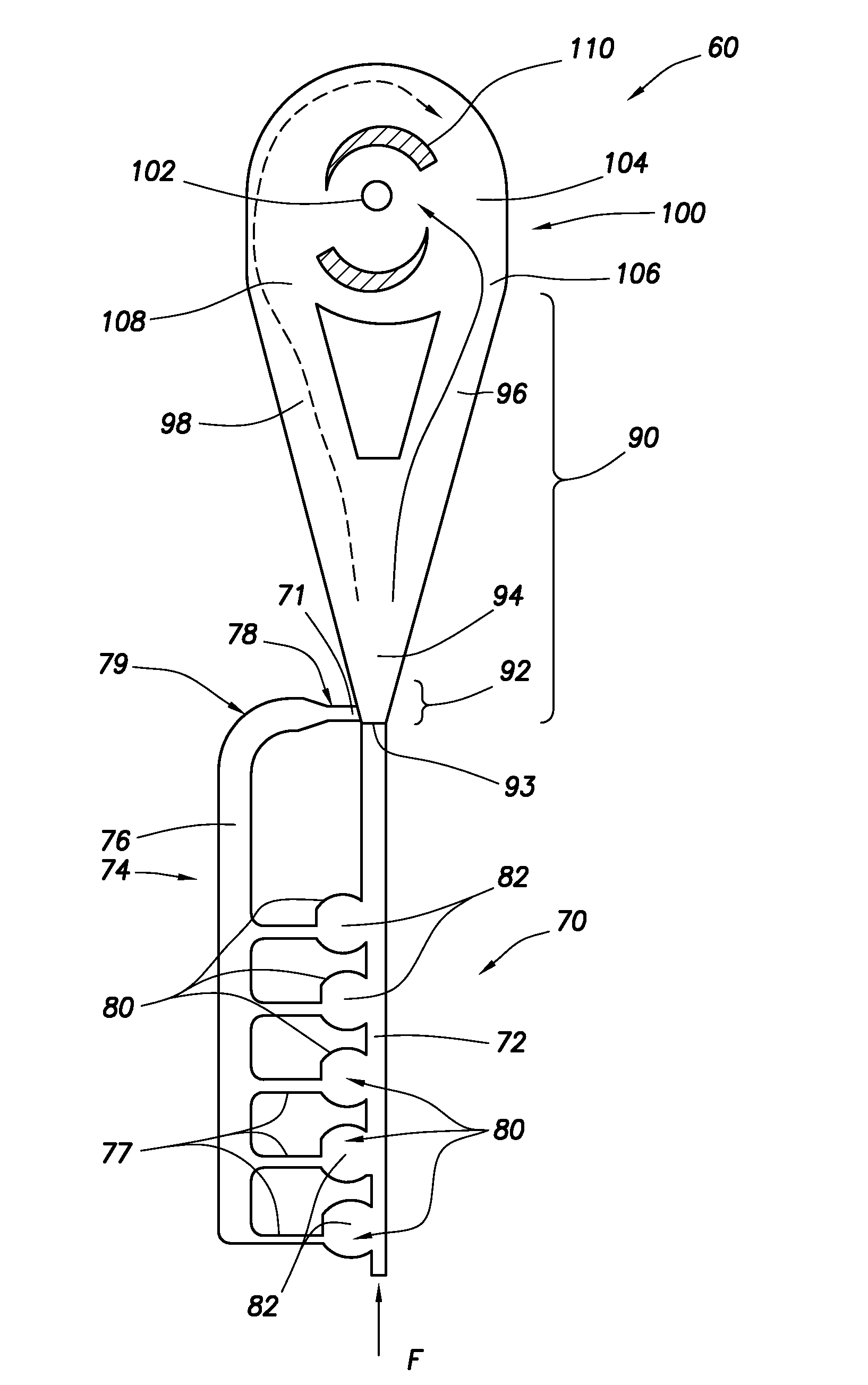
[0007]The downhole tubular can include a plurality of flow control systems. The flow control systems can be used in production and injection methods. The flow control systems autonomously select for fluid of a desired characteristic as that characteristic changes over time.

Problems solved by technology

Similar issues arise with regard to injection situations, with flow of fluids going into instead of out of the formation.

Method used


Image

  • Method and apparatus for controlling fluid flow in an autonomous valve using a sticky switch
  • Method and apparatus for controlling fluid flow in an autonomous valve using a sticky switch
  • Method and apparatus for controlling fluid flow in an autonomous valve using a sticky switch

Examples


Embodiment Construction

[0021]While the making and using of various embodiments of the present invention are discussed in detail below, a practitioner of the art will appreciate that the present invention provides applicable inventive concepts which can be embodied in a variety of specific contexts. The specific embodiments discussed herein are illustrative of specific ways to make and use the invention and do not limit the scope of the present invention.

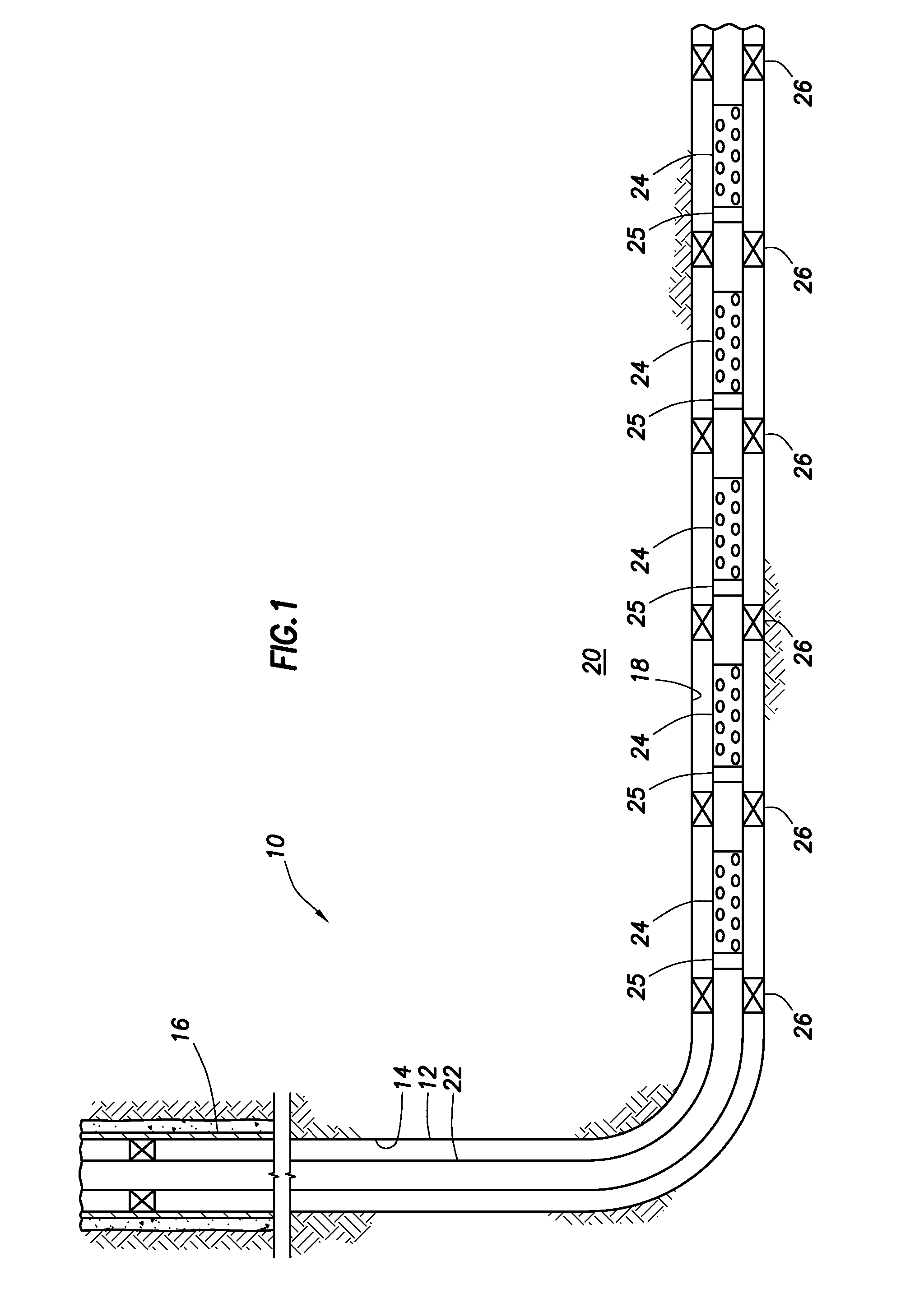
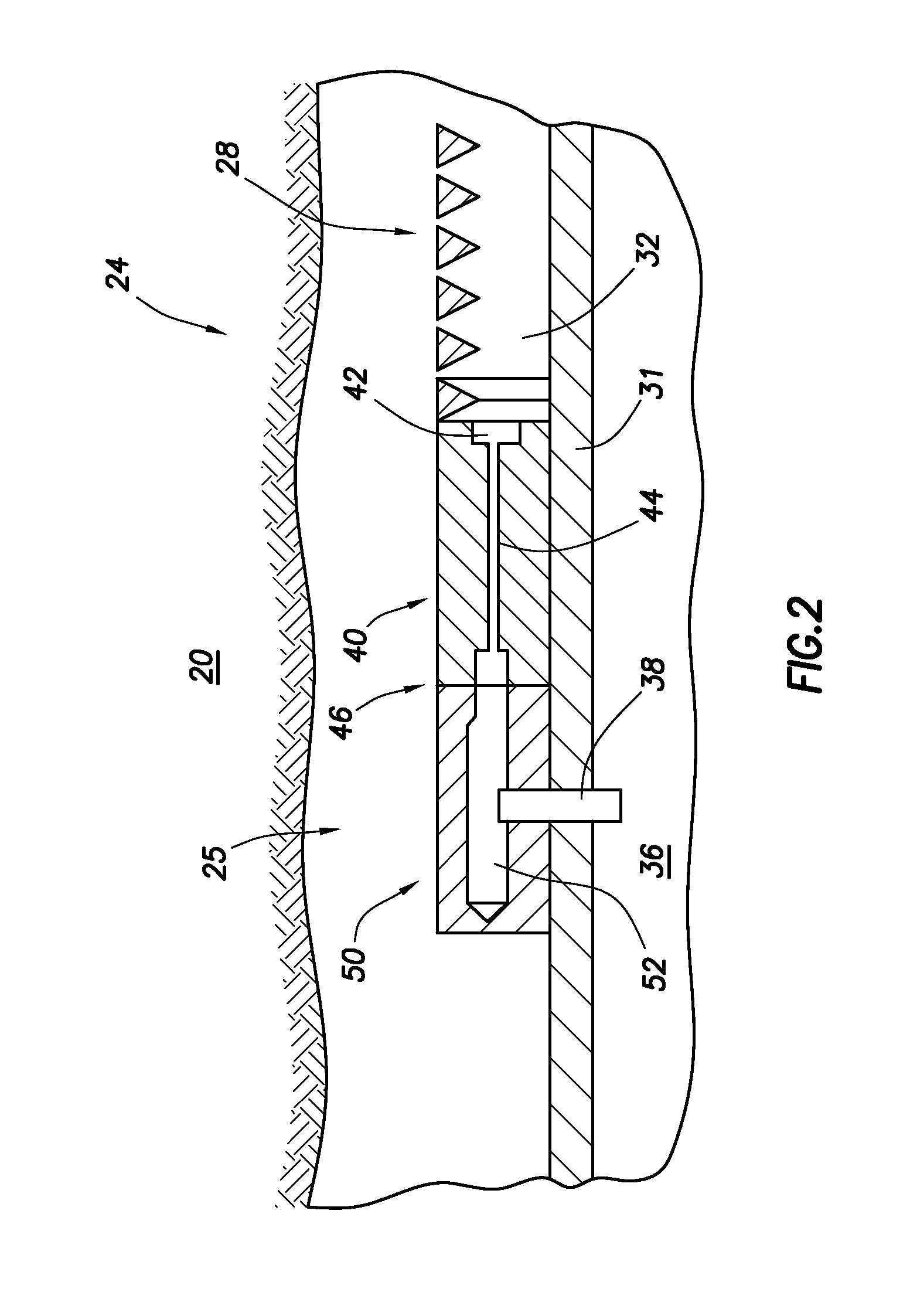
[0022]FIG. 1 is a schematic illustration of a well system, indicated generally 10, including a plurality of autonomous flow control systems embodying principles of the present invention. A wellbore 12 extends through various earth strata. Wellbore 12 has a substantially vertical section 14, the upper portion of which has installed therein a casing string 16. Wellbore 12 also has a substantially deviated section 18, shown as horizontal, which extends through a hydrocarbon-bearing subterranean formation 20. As illustrated, substantially horizontal section 18...


PUM


Abstract

Apparatus and methods are described for autonomously controlling fluid flow in a tubular in a wellbore. A fluid is flowed through an inlet passageway into a biasing mechanism. A fluid flow distribution is established across the biasing mechanism. The fluid flow distribution is altered in response to a change in the fluid characteristic over time. In response, fluid flow through a downstream sticky switch assembly is altered, thereby altering fluid flow patterns in a downstream vortex assembly. The method “selects” based on a fluid characteristic, such as viscosity, density, velocity, flow rate, etc. The biasing mechanism can take various forms such as a widening passageway, contour elements along the biasing mechanism, or a curved section of the biasing mechanism passageway. The biasing mechanism can include hollows formed in the passageway wall, obstructions extending from the passageway wall, fluid diodes, Tesla fluid diodes, a chicane, or abrupt changes in passageway cross-section.

Description

CROSS-REFERENCE TO RELATED APPLICATIONS[0001]This application claims priority to U.S. provisional application Ser. No. 61 / 473,669, filed Apr. 8, 2011, which is incorporated herein by reference for all purposes.FIELD OF INVENTION[0002]The invention relates generally to methods and apparatus of control of an autonomous fluid valve using a “sticky switch” or biasing mechanism to control fluid flow, and more specifically to use of such mechanisms to control fluid flow between a hydrocarbon bearing subterranean formation and a tool string in a wellbore.BACKGROUND OF INVENTION[0003]During the completion of a well that traverses a hydrocarbon bearing subterranean formation, production tubing and various equipment are installed in the well to enable safe and efficient production of the fluids. For example, to prevent the production of particulate material from an unconsolidated or loosely consolidated subterranean formation, certain completions include one or more sand control screens posit...

Claims


Application Information

Patent Timeline
IPC IPC(8): E21B34/08
CPCE21B43/12E21B43/14
Inventor FRIPP, MICHAEL L.DYKSTRA, JASON D.
Owner HALLIBURTON ENERGY SERVICES INC
Learn More