

Charge balancing for arbitrary waveform generator & neural stimulation application
a charge balancing and waveform generator technology, applied in the field of charge balancing, can solve the problems of limited waveform limitations of neural stimulators used in other medical applications, and achieve the effect of simple and efficient adjustment of amplitude and pulse width
- Summary
- Abstract
- Description
- Claims
- Application Information
AI Technical Summary
Benefits of technology
Problems solved by technology
Method used
Image

Examples
Embodiment Construction
[0057]Disclosed is a device, or system of devices cooperating with each other, for providing a flexible and highly adaptable stimulation waveform, such as might be used for medical purposes such as spinal stimulation (such as for pain reduction, for example). This system includes a neurostimulation pulse generator that uses digital waveform synthesis techniques to generate stimulation pulses with programmable waveshapes.
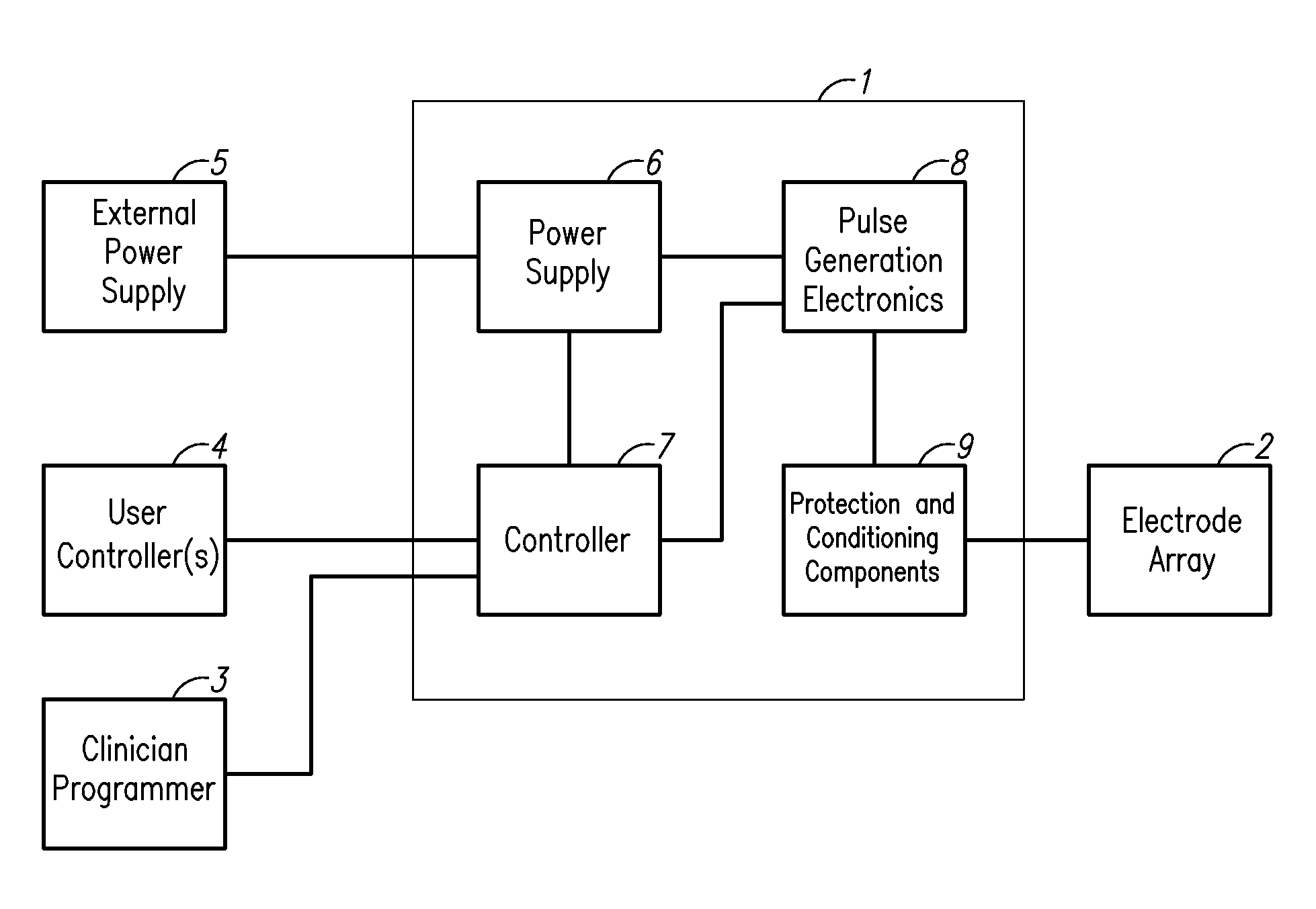
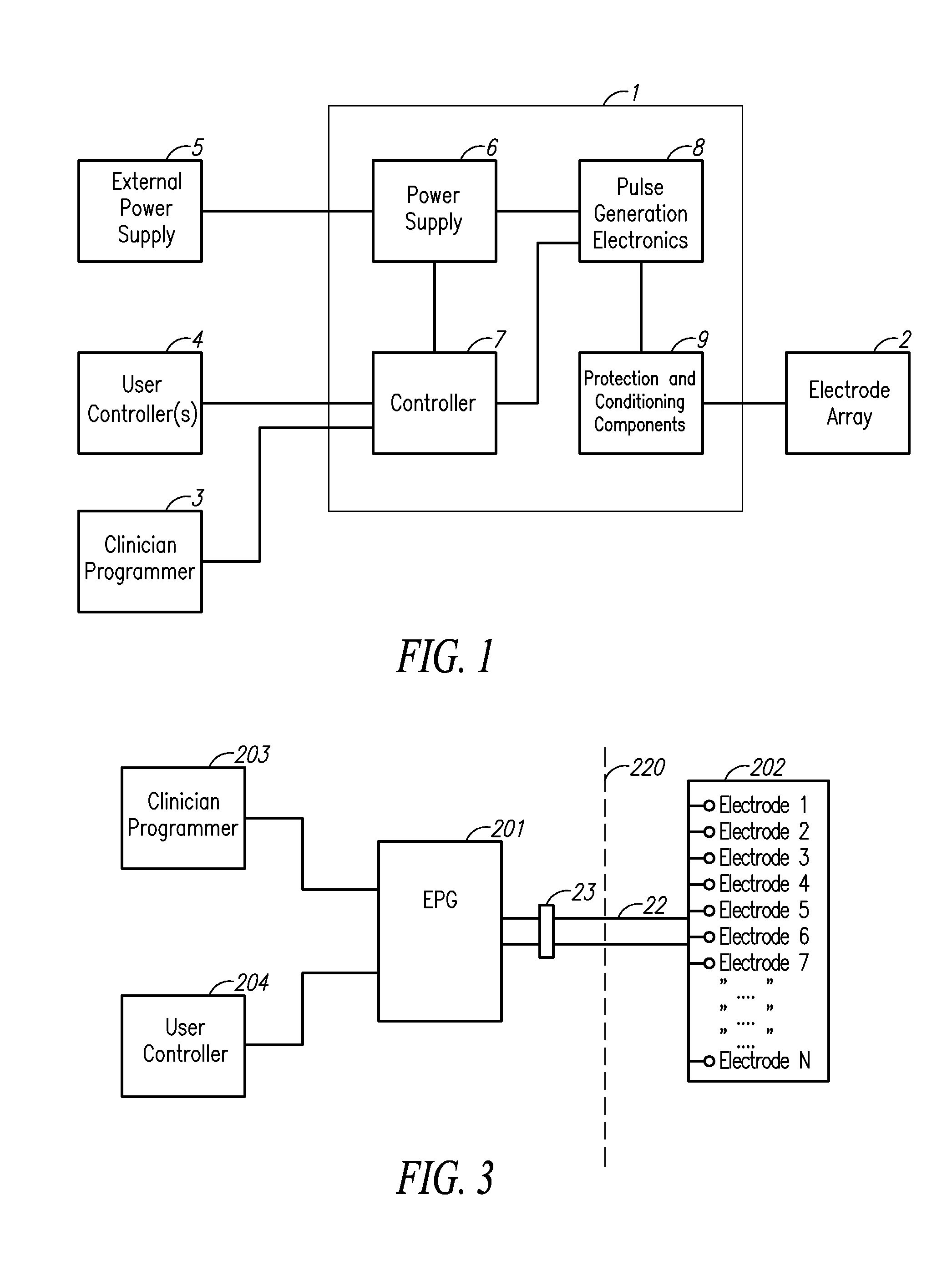
[0058]FIG. 1 is a generic diagram of an example stimulation system. Such a system includes a Pulse Generator (PG) component 1, a set of two or more electrodes (which may include the PG's enclosure) 2, external programming and user controlling devices 3, 4, and a connection to an external power supply 5. The Pulse Generator 1 is typically generally comprised of an internal power supply 6, a controller 7, Pulse Generator electronics 8, and a protection circuit 9.
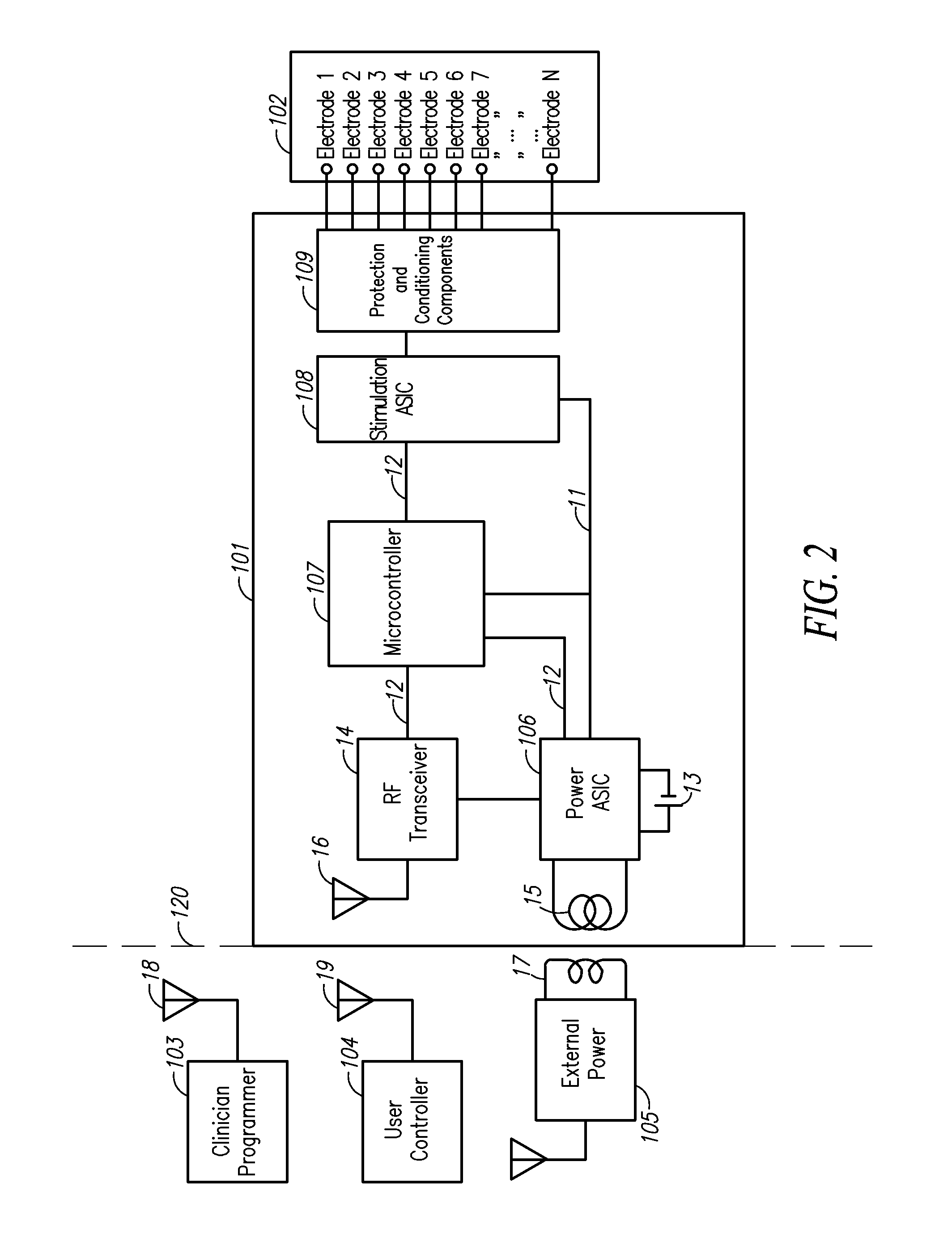
[0059]FIG. 2 shows a more specific example system where most of the components for generating the stimulatio...
PUM
 Abstract
Description
Claims
Application Information