Electrical system with circuit limiter

a technology of circuit limiter and electrical system, which is applied in the direction of constant-current supply dc circuit, coupling device connection, manufacturing tools, etc., can solve the problems of increasing the difficulty of wire management, increasing the difficulty of supplying electrical power, and reducing the electrical resistance across the signal conductor. , the effect of increasing the electrical resistance across the signal conductor

Active Publication Date: 2012-10-18
BYRNE NORMAN R
View PDF1 Cites 40 Cited by
  • Summary
  • Abstract
  • Description
  • Claims
  • Application Information

AI Technical Summary

Benefits of technology

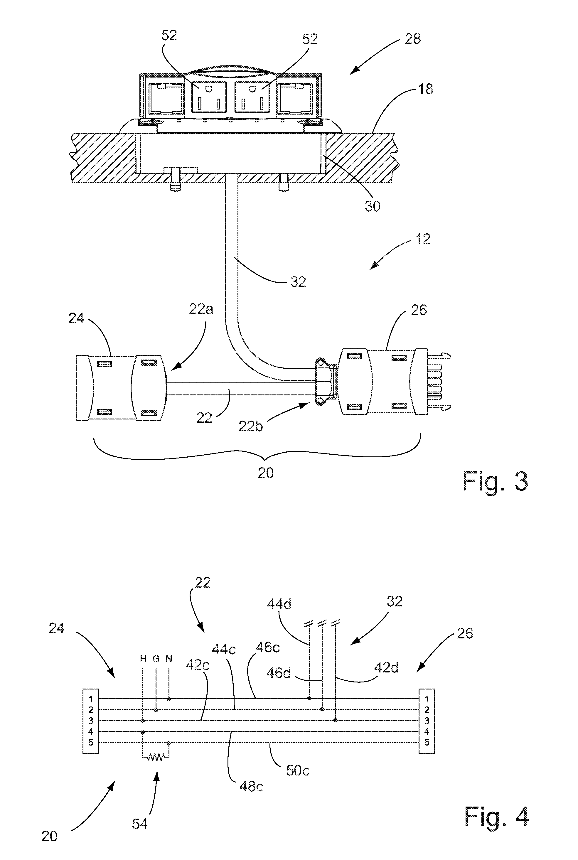
[0010]Optionally, the electrical impedance element is electrically coupled across the signal conductors so that when the electrical power distribution system includes a plurality of main power cable subassemblies electrically coupled in series, the electrical impedance elements are electrically coupled in parallel. In this arrangement, the electrical resistance across the signal conductors is reduced as the total number of main power cable subassemblies and electrical impedance elements is increased.
[0011]Optionally, the electrical impedance element is electrically coupled along only one of the signal conductors so that when the electrical power distribution system includes a plurality of the main power cable subassemblies electrically coupled in series, the electrical impedance elements are also electrically coupled in series. In this arrangement, the electrical resistance across the signal conductors is increased as the total number of main power cable subassemblies and electrical impedance elements is increased.
[0020]Therefore, the present invention provides an electrical power distribution system that may be implemented along a work surface or other area where multiple power outlet receptacles are desired, but which will automatically not energize any of the power outlet receptacles if too many power cable assemblies are connected together in a single circuit. This substantially limits or prevents the chance of a power overload condition, or of too many electrical contact connections being made in a single circuit, while still allowing for the convenience of substantially identical or universal or interchangeable power cable assemblies.

Problems solved by technology

Efficient organization of devices requiring electrical power within an office, commercial, industrial or residential environment has been a historical problem.
The primary problems associated with the efficient organization and use of such devices relate to the abundance of wiring arrays and the positioning of the energy requiring devices within the environment.
The task of wire management has become more troublesome, yet more essential.
A somewhat more of a unique problem arises in the case of ganged or interconnected furniture.
With this type of ganged furniture, problems arise as to how to provide electrical power to each of the computers throughout the length of the connected furniture.
However, in many conference or training rooms, there are not enough wall outlets to accommodate the number of participants.
However, even with such a configuration, and in a conference room setting where there are a dozen or more participants, several power strips would be required.
Still further, even if there are a sufficient number of wall outlets, the use of multiple power strips can still lead to a tangled mass of electrical cables.
Unfortunately, some users may be tempted to improperly “daisy-chain” a set of power strips together.
Such use of a power strip is often in violation of certain regulatory standards, as well as the recommendations of the manufactures of power strips.
Notwithstanding the safety hazards, the daisy-chaining of power strips still presents problems in wire management.

Method used


Image

  • Electrical system with circuit limiter
  • Electrical system with circuit limiter
  • Electrical system with circuit limiter

Examples


Embodiment Construction

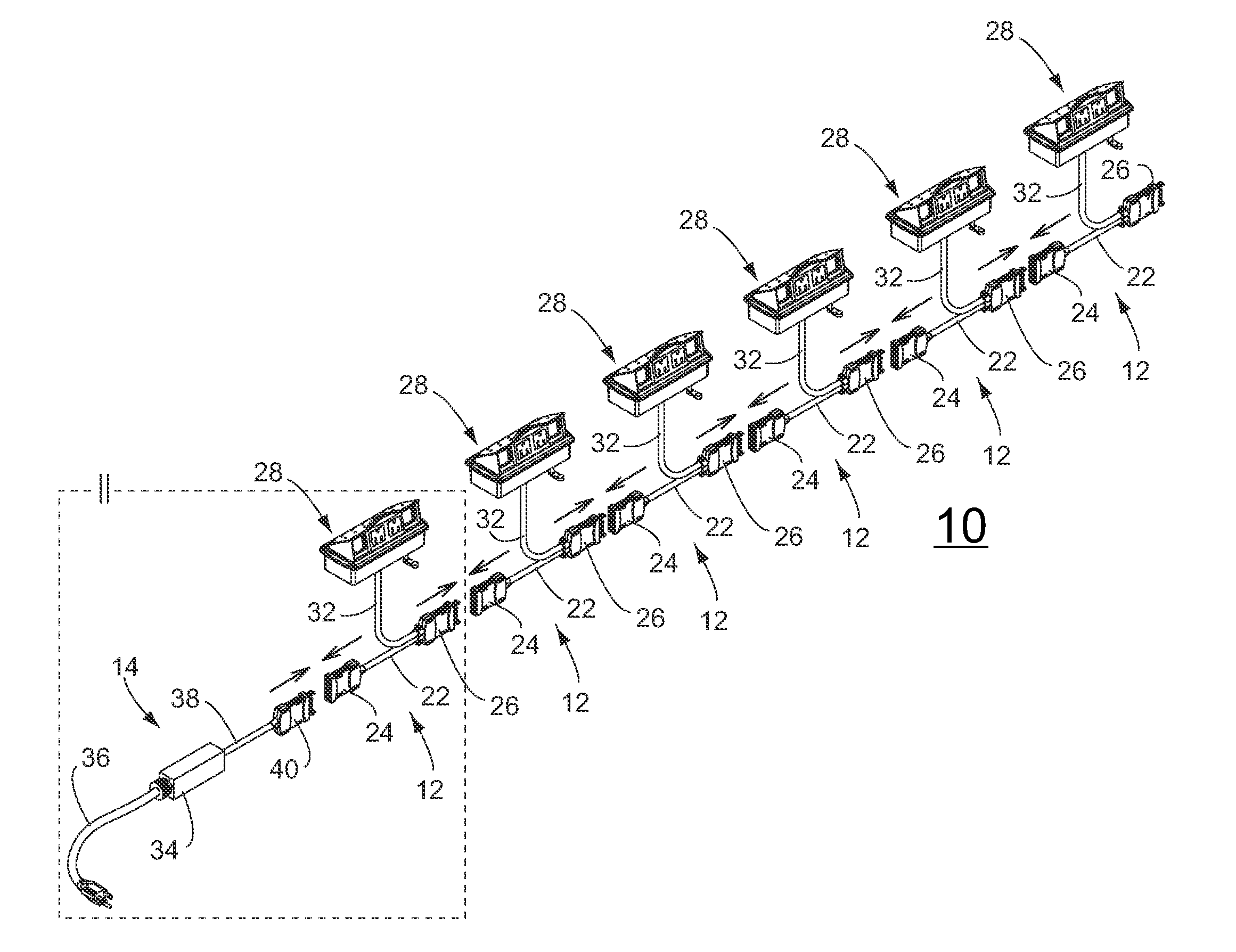
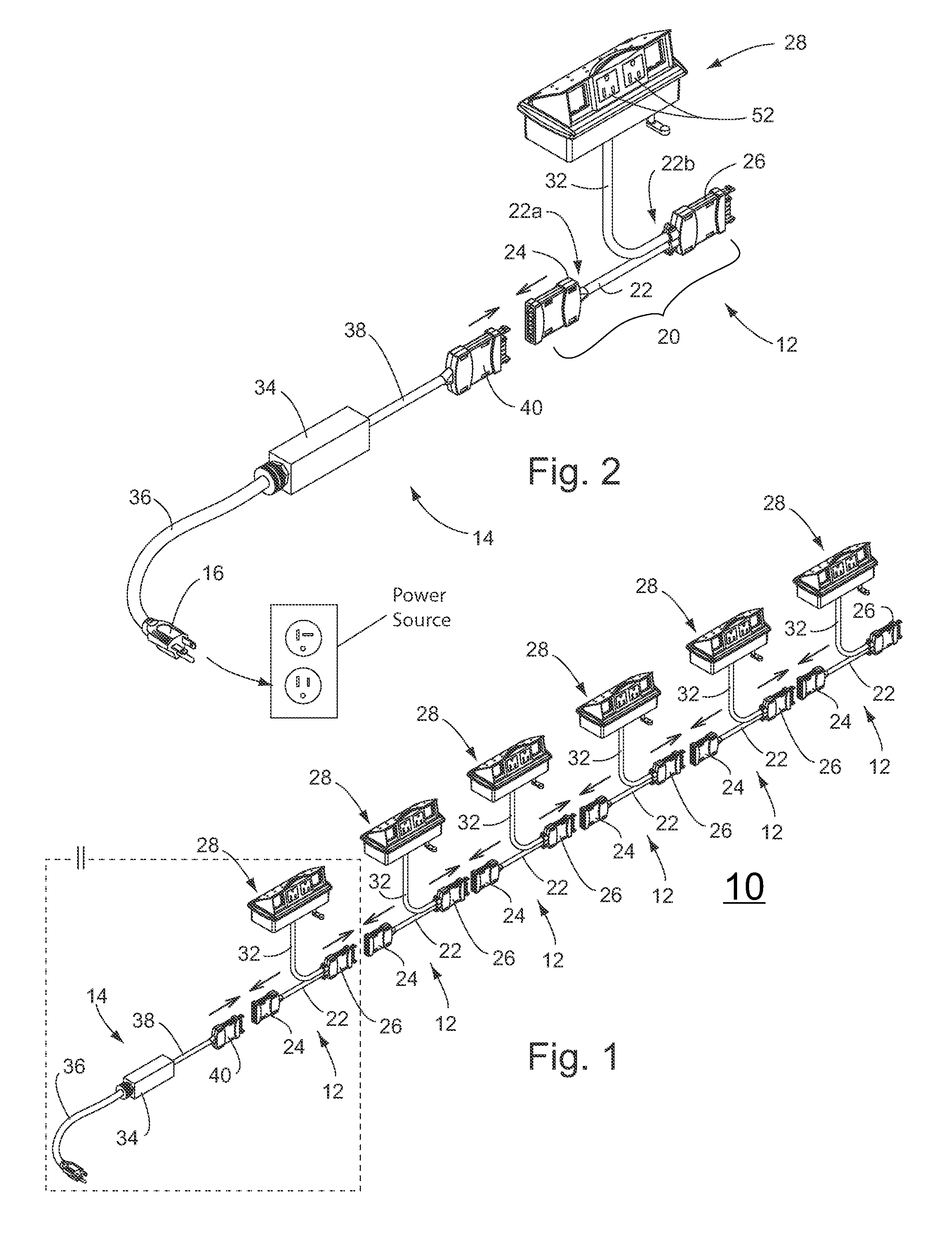
[0032]Referring now to the drawings and the illustrative embodiments depicted therein, an electrical power distribution system 10 includes a plurality of generally Y-shaped power cable assemblies 12 that are electrically connectable together in series, and which receive electrical power via a control unit 14 and direct this power to respective branch cables and a power outlets (FIGS. 1 and 2). Control unit 14 receives electrical power through a plug 16 that is connectable to a wall outlet or other electrical power source (FIG. 2), and is operable to selectively conduct the electrical power to the power cable assemblies 19 depending on the number of power cable assemblies that are coupled together in the electrical power distribution system 10, as will be described in greater detail below. In this way, each power cable assembly 12 can be substantially identical to the other power cable assemblies, and the system 10 can de-energize (or not energize) the power cable assemblies 12 in th...


PUM

PropertyMeasurementUnit
voltageaaaaaaaaaa
voltageaaaaaaaaaa
voltageaaaaaaaaaa

Abstract

An electrical power distribution system automatically limits the number of substantially similar or identical power cable assemblies that are electrically energizable from a power source. A control unit is connected between the power source and the power cable assemblies, and limits the number of power cable assemblies that can be energized in the system by sensing the voltage in a sensing circuit. An applied voltage in the sensing circuit changes in a predictable manner corresponding to the number of power cable assemblies that are electrically connected in the circuit. Each power cable assembly includes an impedance element that is added to the sensing circuit when the corresponding power cable assembly is coupled to the system, and once the detected voltage is beyond a predetermined threshold value, the control unit will ensure that the power cable assemblies are not energized by the power source.

Description

CROSS-REFERENCE TO RELATED APPLICATION[0001]The current application claims the benefit of U.S. provisional application Ser. No. 61 / 476,613, filed Apr. 18, 2011, which is hereby incorporated herein by reference in its entirety.FIELD OF THE INVENTION[0002]The present invention relates to electrical systems for interconnecting modular energy assemblies in tandem, or ganged, and more particularly, to an electrical system for limiting the number of interconnected modular energy assemblies that can be operatively connected to one another.BACKGROUND OF THE INVENTION[0003]Efficient organization of devices requiring electrical power within an office, commercial, industrial or residential environment has been a historical problem. Such devices include lamps, typewriters, computers, printers, complex telephone stations, video displays, and the like. The primary problems associated with the efficient organization and use of such devices relate to the abundance of wiring arrays and the positioni...

Claims


Application Information

Patent Timeline
Patent Type & Authority Applications(United States)
IPC IPC(8): H02J4/00H02B1/24
CPCH02J3/00H01R13/6616H01R25/168H01R25/003H01R13/70
Inventor BYRNE, NORMAN R.WARWICK, TIMOTHY J.GIBSON, SHAWN R.
Owner BYRNE NORMAN R
Why Eureka
Try Eureka