Battery and method of manufacturing the same

a battery and manufacturing method technology, applied in the field of batteries, can solve the problems of defective sealing, reduced battery performance, and thread ridge of the bolt portion

Active Publication Date: 2012-10-18
GS YUASA INT LTD
View PDF9 Cites 47 Cited by
  • Summary
  • Abstract
  • Description
  • Claims
  • Application Information

AI Technical Summary

Benefits of technology

[0016]An object of the present invention is to provide a battery capable of baffling an external terminal using a baffling portion disposed projecting on a lid plate, so that fastening torque of the external terminal would not impair airtightness and conductivity, and a method of manufacturing such a battery.

Problems solved by technology

The external terminal 4 running idle causes a problem of reduced battery performance due to an increased contact electrical resistance between the external terminal 4 and the current collecting connector 5, as well as a problem of defective sealing within the battery container 1 due to a gap occurring between the insulating and sealing members 6 and 7.
In addition, as aluminum alloy is often used for the external terminal 4 on the positive electrode side in the case of the nonaqueous electrolyte secondary battery, there is another problem that when the bolt portion 4b is tightly fastened by a nut or the like, or when such a nut is repeatedly attached and detached, a thread ridge of the bolt portion 4b is often damaged.
However, even with such an attachment structure of the external terminal 4, there is a problem that the external terminal 4 possibly runs idle by a small amount of angle due to a small gap in the fitting between the base portion 4a and the external terminal recessed portion of the external insulating and sealing member 6, and it is not possible to completely prevent the caulking between the tube 4c and the connecting portion 5a of the current collecting connector 5 from becoming loose.
In addition, there is another problem that when the bolt portion 4b is fastened by a nut or the like, the fastening torque is directly applied to the external insulating and sealing member 6 to apply a significant stress to the external insulating and sealing member6, and whereby airtightness become impaired.
Therefore, it is necessary that the attachment of the external terminal and the insertion of the projecting portion into the recessed hole be carried out within the battery container, posing a problem that the battery assembly is difficult.
However, as a result of a great deal of consideration, there is a problem even in the attachment structure of the external terminal 4 as described above that as the fastening torque is directly applied to the external terminal recessed portion 6a of the external insulating and sealing member 6 when the bolt portion 4b is fastened by a nut or the like, a significant stress is applied by to the external insulating and sealing member 6 that seals between the auxiliary terminal 8 and the lid plate 3 by swaging the first tube 8b of the auxiliary terminal 8, and therefore it is not possible to prevent high level of airtightness from being impaired.

Method used


Image

  • Battery and method of manufacturing the same
  • Battery and method of manufacturing the same
  • Battery and method of manufacturing the same

Examples


Embodiment Construction

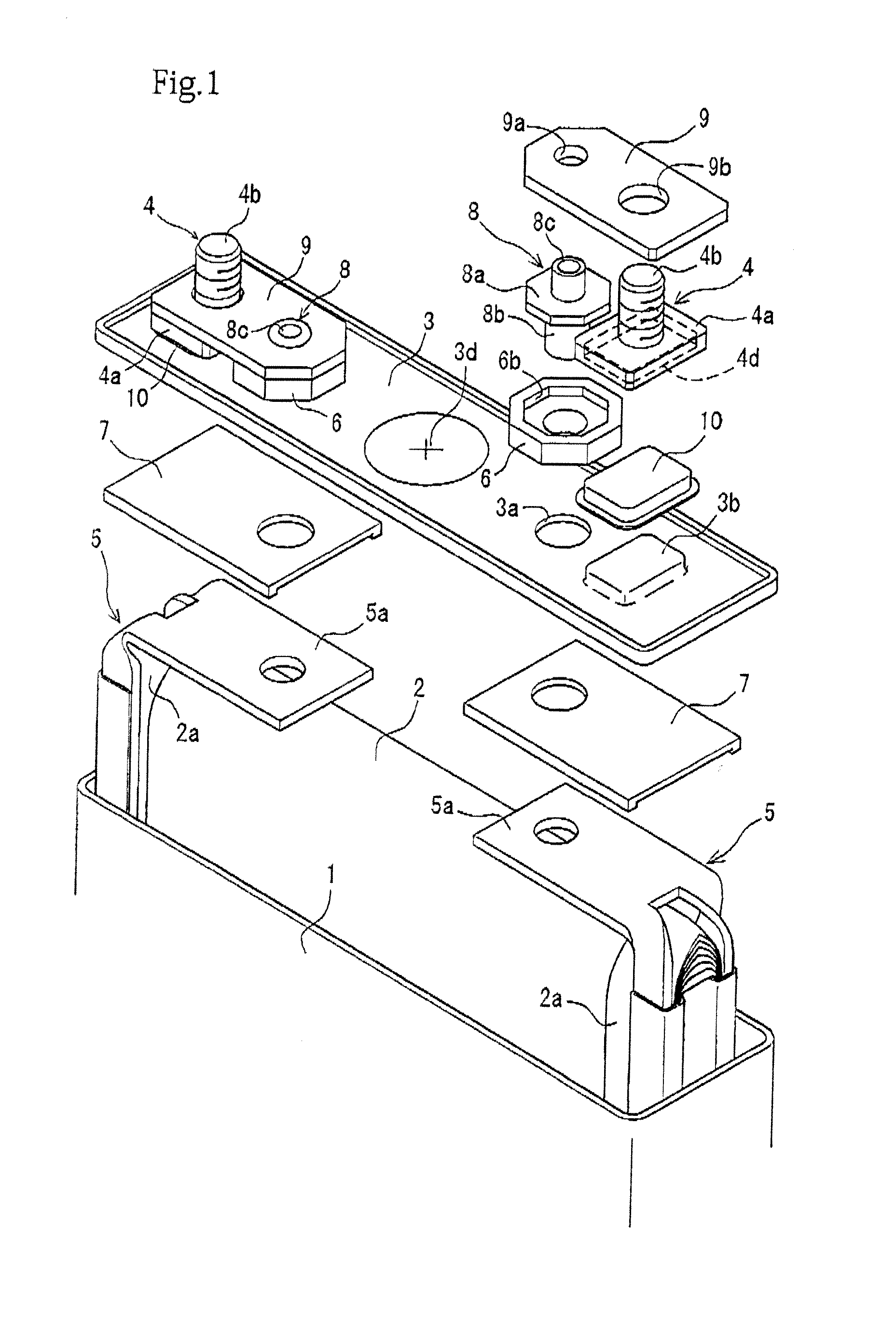
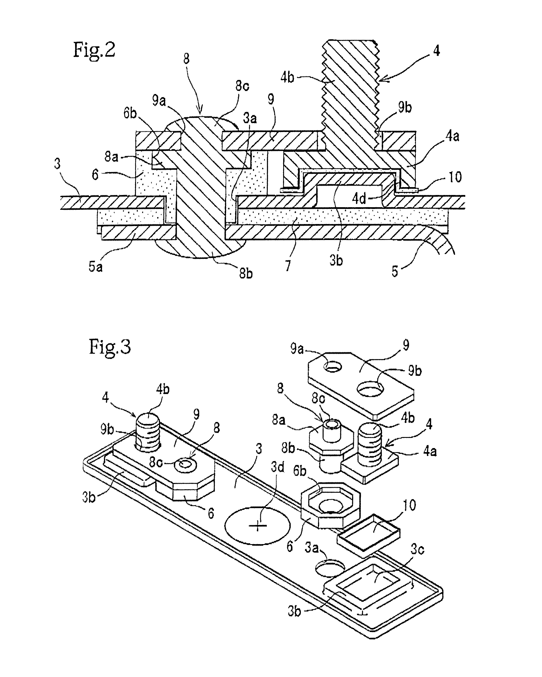
[0036]Preferred embodiments of the present invention will be described hereinafter with reference to FIG. 1 to FIG. 6. Throughout the figures, like components having functions as those of the conventional examples illustrated in FIG. 7 and FIG. 8 are denoted by like reference numerals.

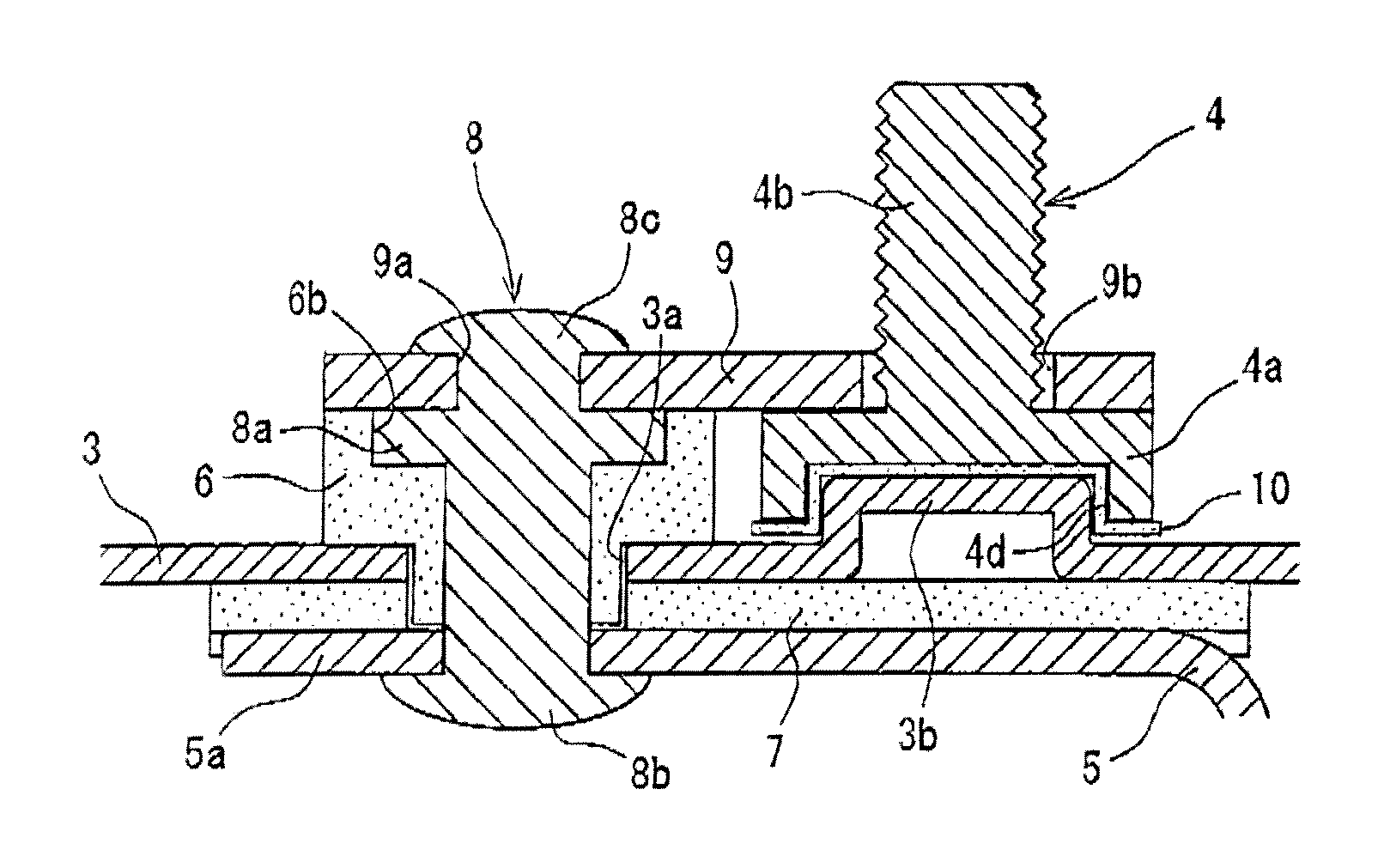
[0037]This embodiment describes a large-sized nonaqueous electrolyte secondary battery. Referring to FIG. 1 and FIG. 2, the nonaqueous electrolyte secondary battery is configured such that a battery container 1 contains an elliptic cylindrical winding power generating element 2, and sealed by a lid plate 3 covering a top opening of the battery container 1.

[0038]The power generating element 2 is configured such that a positive electrode and a negative electrode as belt-shaped electrodes are displaced in different directions of right and left with a separator interposed therebetween and wound centering a rotation axis along a right and left direction in an elliptic cylindrical shape so as to form an elli...


PUM

PropertyMeasurementUnit
metallicaaaaaaaaaa
electrical resistanceaaaaaaaaaa
angleaaaaaaaaaa

Abstract

The present invention provides a battery that includes: a lid plate provided with a terminal pull-out through hole and a baffling portion whose upper surface is configured in a projecting and / or recessed manner; an auxiliary terminal configured such that a lower portion thereof is connected to a metallic foil of a power generating element by being fitted into a battery container through the terminal pull-out through hole, and sealed and fixed to the lid plate by insulating and sealing members; a connecting conductor connected and fixed to an upper portion of the auxiliary terminal; and an external terminal having a bolt portion that projects upward from a base portion, the bolt portion being inserted through the terminal through hole of the connecting conductor from below, and the base portion being engaged with the baffling portion of the lid plate, thereby restricting rotation centering an axial line of the bolt portion.

Description

BACKGROUND OF THE INVENTION[0001]1. Field of the Invention[0002]The present invention relates to a battery in which a terminal is provided for a lid plate covering a top opening of a battery container containing a power generating element.[0003]2. Description of the Related Art[0004]FIG. 7 shows an attachment structure of a terminal for a conventional large-sized nonaqueous electrolyte secondary battery (see FIG. 6 to FIG. 8 in JP-A-2001-357833, for example). This nonaqueous electrolyte secondary battery is configured such that an elliptic cylindrical winding power generating element 2 is contained within a battery container 1 and a top opening of the battery container 1 is covered and sealed by a lid plate 3. At both right and left ends of the power generating element 2, metallic foils 2a, 2a of electrodes respectively protrude in a wound state. These metallic foils 2a, 2a are connected to current collecting connectors 5, 5. Further, to both right and left ends of the lid plate 3, ...

Claims


Application Information

Patent Timeline
Patent Type & Authority Applications(United States)
IPC IPC(8): H01M2/30H01M50/147H01M50/176
CPCH01M2/043H01M2/0473H01M2/06H01M2/307H01M2/263Y02E60/10H01M50/15H01M50/147H01M50/561H01M50/176
Inventor SASAKI, TAKESHITOZUKA, KAZUHIDEOKAMOTO, KATSUHIKOTSUTSUMI, MASAKAZU
Owner GS YUASA INT LTD
Why Eureka
Try Eureka