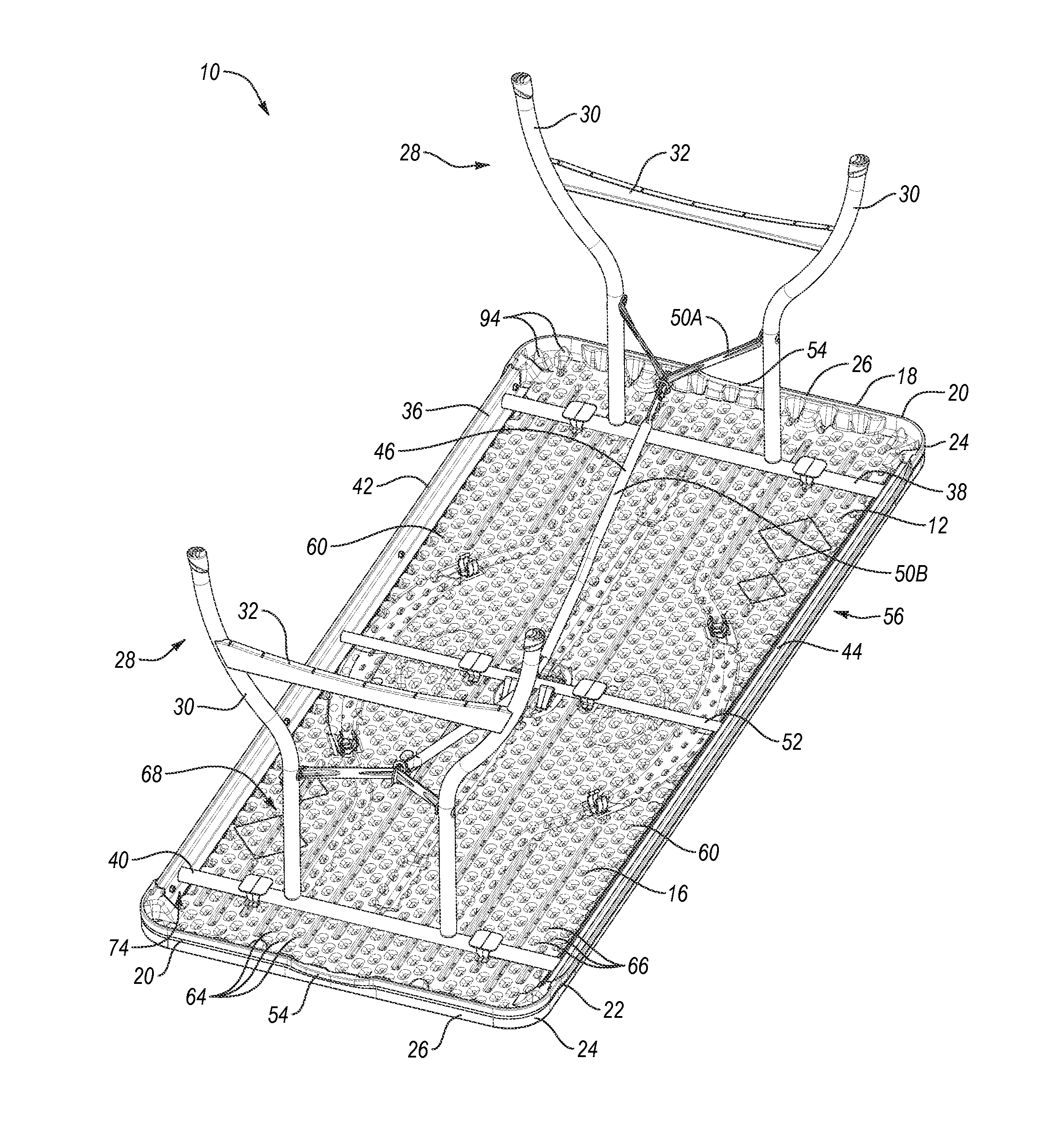
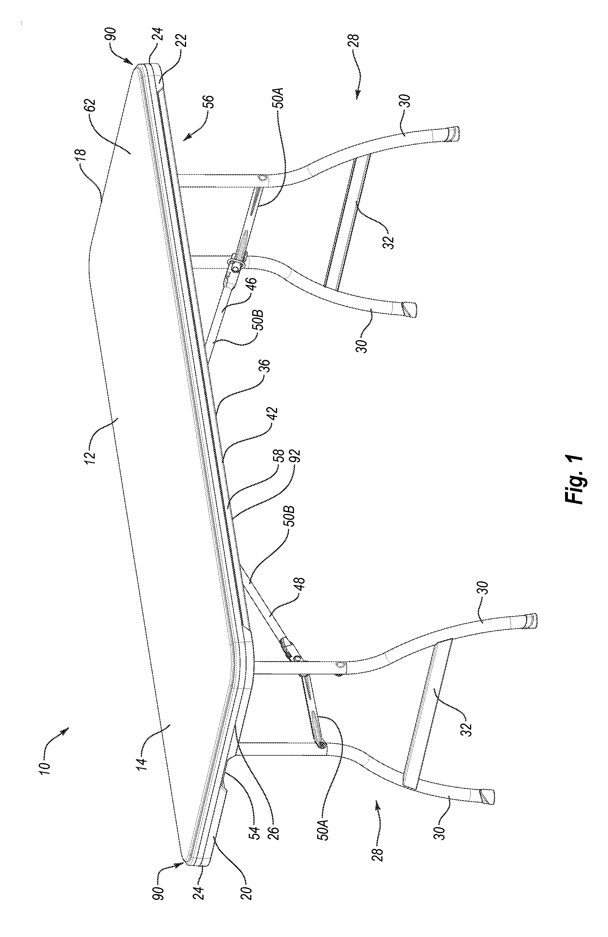
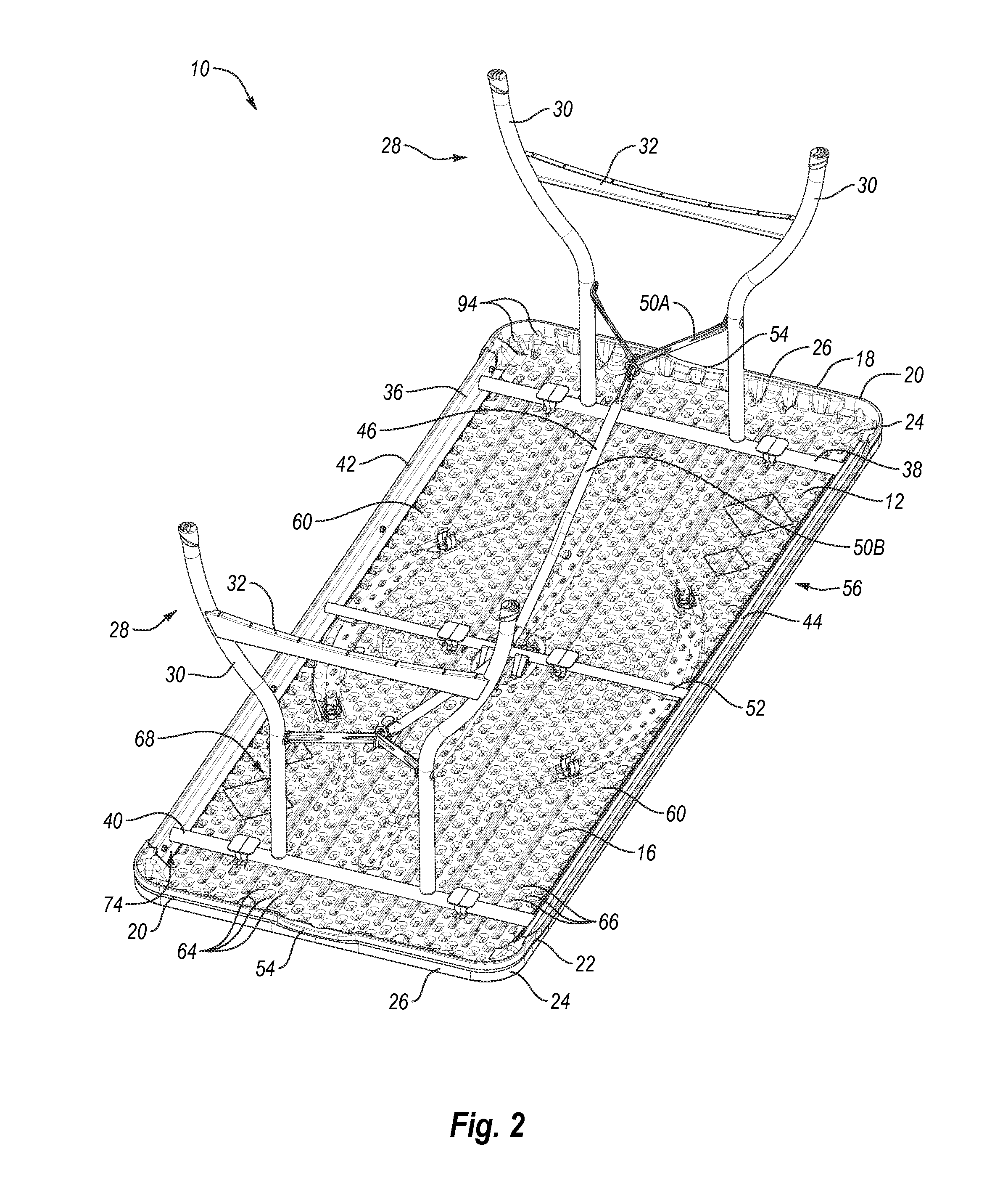
Table top

a table top and table top technology, applied in the field of structures, can solve the problems of reducing the space required to store and/or transport the table, reducing the weight of the table, etc., and achieve the effects of increasing strength, rigidity and/or structural integrity, facilitating alignment and nesting of the tables, and reducing the amount of weight and for

Inactive Publication Date: 2012-10-25
LIFETIME PRODUCTS
View PDF0 Cites 39 Cited by
  • Summary
  • Abstract
  • Description
  • Claims
  • Application Information

AI Technical Summary

Benefits of technology

[0013]One aspect is a table that may include a table top and one or more legs sized and configured to support the table top above a surface such as the floor or ground. The table may also include a frame and legs connected to the frame. The legs may be movable relative to the table top between a collapsed or storage position and an extended or use position. In particular, the legs may be pivoted between a collapsed position in which the legs are disposed at least proximate a lower surface of the table top and an extended position in which the legs extend outwardly from the table top. If desired, the legs may at least partially contact or abut the lower surface of the table top when the legs are in the collapsed position. In addition, the lower surface of the table top may include one or more recesses sized and configured to receive at least a portion of the legs when the legs are in the collapsed position. Advantageously, this may decrease the amount of space required to store and / or transport the table.
[0054]Another further aspect is a table that may include legs with support members that are widely spaced, which may help create a sturdy table that is unlikely to undesirably move or wobble. The table may also include a table top with various shapes, sizes, configurations and arrangements, such as rectangular, square, circular, oblong and the like. In addition, the table top may include one or more openings to allow, for example, a portion of the frame to be exposed and / or to create a handle or grip.

Problems solved by technology

Advantageously, this may decrease the amount of space required to store and / or transport the table.
Further, a limited number of fasteners may be required to assemble the table, which may also reduce the weight of the table.

Method used


Image

  • Table top
  • Table top
  • Table top

Examples


Embodiment Construction

[0076]The present invention is generally directed towards tables. The principles of the present invention, however, are not limited to tables. It will be understood that, in light of the present disclosure, the tables disclosed herein can have a variety of shapes, sizes, configurations and arrangements. In addition, while the tables shown in the accompanying figures are banquet or utility tables, it will be appreciated the tables may have any suitable style or configuration such as round, personal, conference or card tables. Further, the invention disclosed herein may be successfully used in connection with other types of furniture and / or structures.

[0077]Additionally, to assist in the description of preferred embodiments of the tables, words such as top, bottom, front, rear, right and left may be used to describe the accompanying figures which may be, but are not necessarily, drawn to scale. It will further be appreciated the tables can be disposed in a variety of desired positions...


PUM


Abstract

A table may include a table top with a first plurality of depressions aligned in a plurality of generally aligned rows. The table top may also include a plurality of channels disposed generally parallel to the rows of depressions and each channel may have a width generally equal to a width of the first plurality of depressions. The table top may further include a second plurality of depressions disposed in the channels. The table top may further include a recess sized and configured to receive a structural support member, and a portion of the channels may be disposed on both sides of the recess.

Description

CROSS-REFERENCE TO RELATED APPLICATIONS[0001]The present application claims priority to and the benefit of U.S. provisional patent application Ser. No. 61 / 478,786, entitled TABLE, which was filed on Apr. 25, 2011; U.S. provisional patent application Ser. No. 61 / 478,879, entitled TABLES AND CHAIRS, which was filed on Apr. 25, 2011; U.S. design patent application Ser. No. 29 / 390,471, entitled PORTION OF A TABLE TOP, which was filed on Apr. 25, 2011; U.S. provisional patent application Ser. No. 61 / 531,081, entitled TABLE, which was filed on Sep. 5, 2011; and U.S. provisional patent application Ser. No. 61 / 543,277, entitled TABLE, which was filed on Oct. 4, 2011; each of which is hereby incorporated by reference in its entirety.BACKGROUND[0002]1. Field of the Invention[0003]The present invention generally relates to structures including at least a portion constructed from plastic and, in particular, to furniture, such as tables and chairs, that may include molded plastic components.[000...

Claims


Application Information

Patent Timeline
Patent Type & Authority Applications(United States)
IPC IPC(8): A47B13/08A47B7/02A47B3/08
CPCA47B3/0912A47B13/08A47B7/02
Inventor PEERY, WENDELLJOHNSON, MITCH
Owner LIFETIME PRODUCTS
Why Eureka
Try Eureka