Active prosthetic socket

a prosthetic socket and active technology, applied in the field of active prosthetic sockets, can solve the problems of ineffective prosthetic sockets, bulky and heavy, and ineffective air-pressurized active prosthetic sockets

Active Publication Date: 2012-10-25
VIVONICS
View PDF5 Cites 75 Cited by
  • Summary
  • Abstract
  • Description
  • Claims
  • Application Information

AI Technical Summary

Problems solved by technology

However, the VASS may not be effective, is bulky and heavy.
However, the air pressurized active prosthetic socket may be ineffective because it is rotationally unstable.
Although the conventional systems discussed above attempt to maintain adequate socket-limb contact during use of the prosthetic socket, they do not account for the shape changes that occur within the residual limb during ambulation or motion.

Method used


Image

  • Active prosthetic socket
  • Active prosthetic socket
  • Active prosthetic socket

Examples


Embodiment Construction

[0021]Aside from the preferred embodiment or embodiments disclosed below, this invention is capable of other embodiments and of being practiced or being carried out in various ways. Thus, it is to be understood that the invention is not limited in its application to the details of construction and the arrangements of components set forth in the following description or illustrated in the drawings. If only one embodiment is described herein, the claims hereof are not to be limited to that embodiment. Moreover, the claims hereof are not to be read restrictively unless there is clear and convincing evidence manifesting a certain exclusion, restriction, or disclaimer.

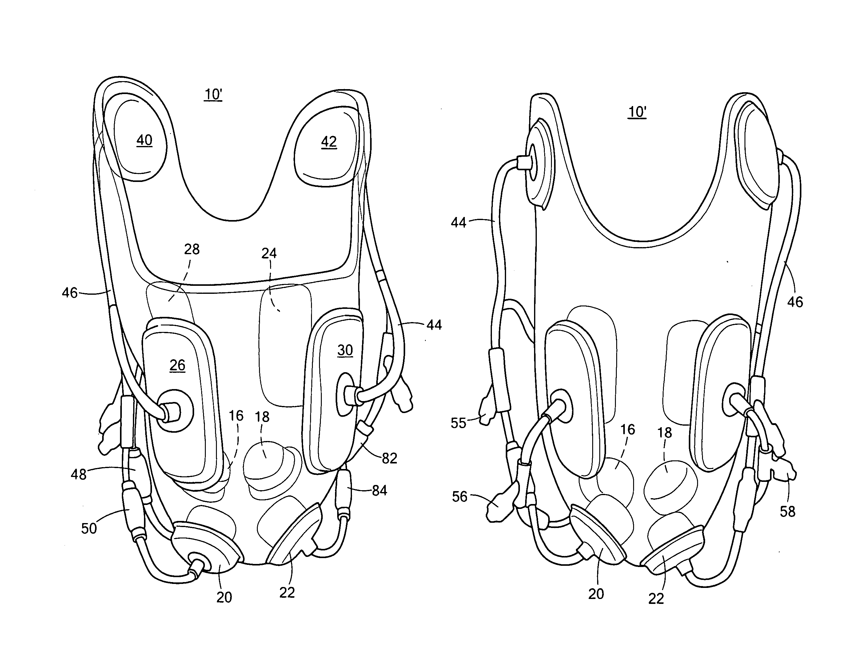
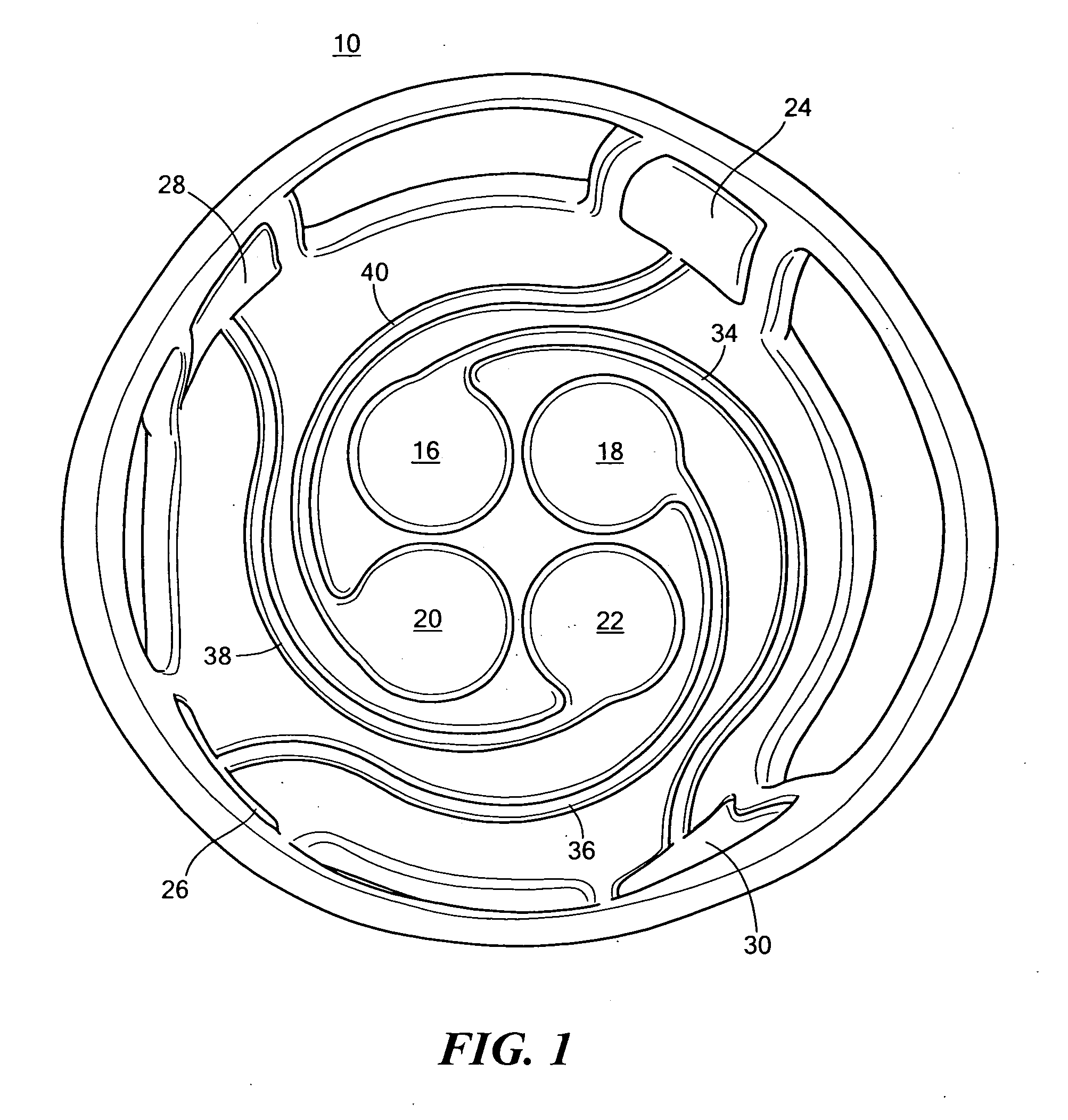
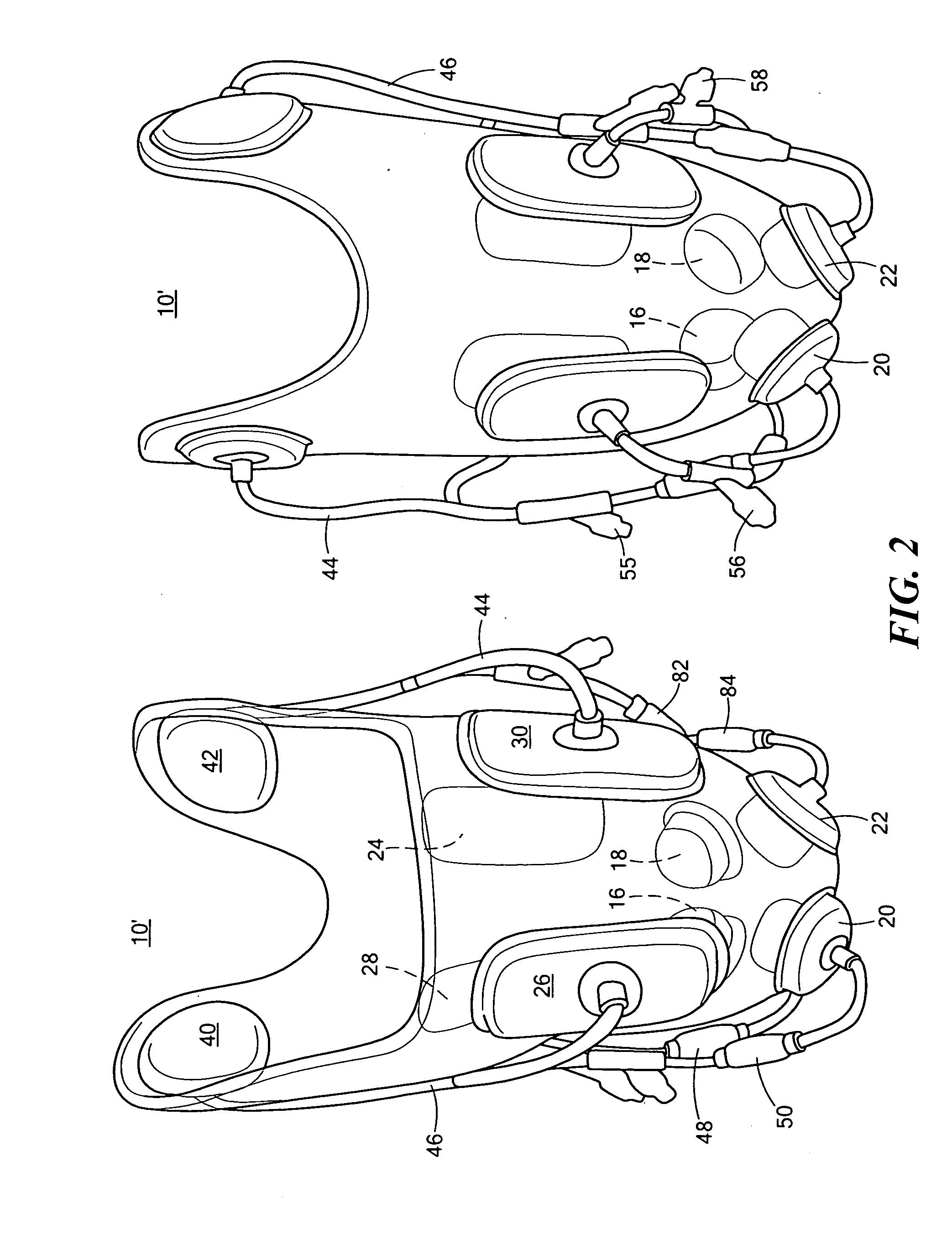
[0022]There is shown in FIG. 1 one embodiment of active prosthetic socket 10 of this invention. Active prosthetic socket 10 includes prosthetic socket 12 shaped to fit a residual limb of an amputee. Prosthetic socket device 10 also includes active adjustment system 14 integrated with prosthetic socket 12 which dynamically a...


PUM


Abstract

An active prosthetic socket including a prosthetic socket shaped to fit a residual limb. An active adjustment system is integrated with the prosthetic socket and is configured to dynamically adjust the fit of the active prosthetic socket to the residual limb of a user during ambulation or motion.

Description

RELATED APPLICATIONS[0001]This application claims benefit of and priority to U.S. Provisional Application Ser. No. 61 / 517,498 filed Apr. 20, 2011, under 35 U.S.C. §§119, 120, 363, 365, and 37 C.F.R. §1.55 and §1.78, incorporated herein by this reference.GOVERNMENT RIGHTS[0002]This invention was made with U.S. Government support under Contract No. W81XWH-07-C-0094 by the Army. The Government may have certain rights in certain aspects of the subject invention.FIELD OF THE INVENTION[0003]This invention relates to an active prosthetic socket.BACKGROUND OF THE INVENTION[0004]One conventional prosthetic socket device which attempts to address residual limb volume changes during ambulation or motion is a vacuum-assisted socket system (VASS). The VASS uses a vacuum to regulate residual limb volume fluctuation and decrease perspiration. However, the VASS may not be effective, is bulky and heavy.[0005]Another conventional prosthetic socket is an air pressurized active prosthetic socket device...

Claims


Application Information

Patent Timeline
Patent Type & Authority Applications(United States)
IPC IPC(8): A61F2/80
CPCA61F2/7812A61F5/01A61F2/80Y10T442/2008
Inventor GALEA, ANNA M.LEROY, KRISTENTRUONG, THIEU Q.
Owner VIVONICS
Why Eureka
Try Eureka