Pump system for prosthesis

a pump system and prosthesis technology, applied in the field of prosthetic pump systems, can solve the problems of slipping or undesired movement of prosthesis relative to limbs, pump systems have limitations compared to more conventional, non-vacuum type systems, and still have various versatility and performance limitations, so as to minimize undesired size changes of residual limbs and increase comfort

Active Publication Date: 2011-02-24
ORTHOCARE INNOVATIONS
View PDF4 Cites 53 Cited by
  • Summary
  • Abstract
  • Description
  • Claims
  • Application Information

AI Technical Summary

Benefits of technology

[0012]The present invention relates to a prosthetic pump system or prosthesis that may advantageously provide a better fit and thus increased comfort with respect to a wearer's limb as well as sense and interpret a variety of the wearer's needs. In one embodiment, the prosthesis includes a pump system that evacuates air from spaces, gaps or other interstices present between the residual limb and the prosthesis while increasing a surface contact area between the same, which in turn may minimize undesired size changes of the residual limb. The pu

Problems solved by technology

However, each of these systems may still have various limitations in versatility and performance.
The “fit” of the prosthesis is one of the major issues that must be dealt with whether in the design of the prosthesis, its control logic, its calibration methods, by the interface between the prosthesis and the limb (e.g., liner or gel sock), or any combination thereof.
As a result of the residual limb changing in size the prosthesis may slip or undesirably move relative to the limb.
However, pump systems do have some limitations as compared to more conventional, non-vacuum type systems.
For example, pump systems may have a less appealing cosmetic or aesthetic appearance, they may be less versatile, they may have a higher mass, and higher audible or inaudible noise levels.
In addition, control systems used in conjunction with the pump systems may not adequately replicate or respond to natural human locomotion due to dynamic loading, impact or shock loading, or complex load cycles that may be generated by active individuals.
While this approach may provide a comfortable fit, it incorporat

Method used


Image

  • Pump system for prosthesis
  • Pump system for prosthesis
  • Pump system for prosthesis

Examples


Embodiment Construction

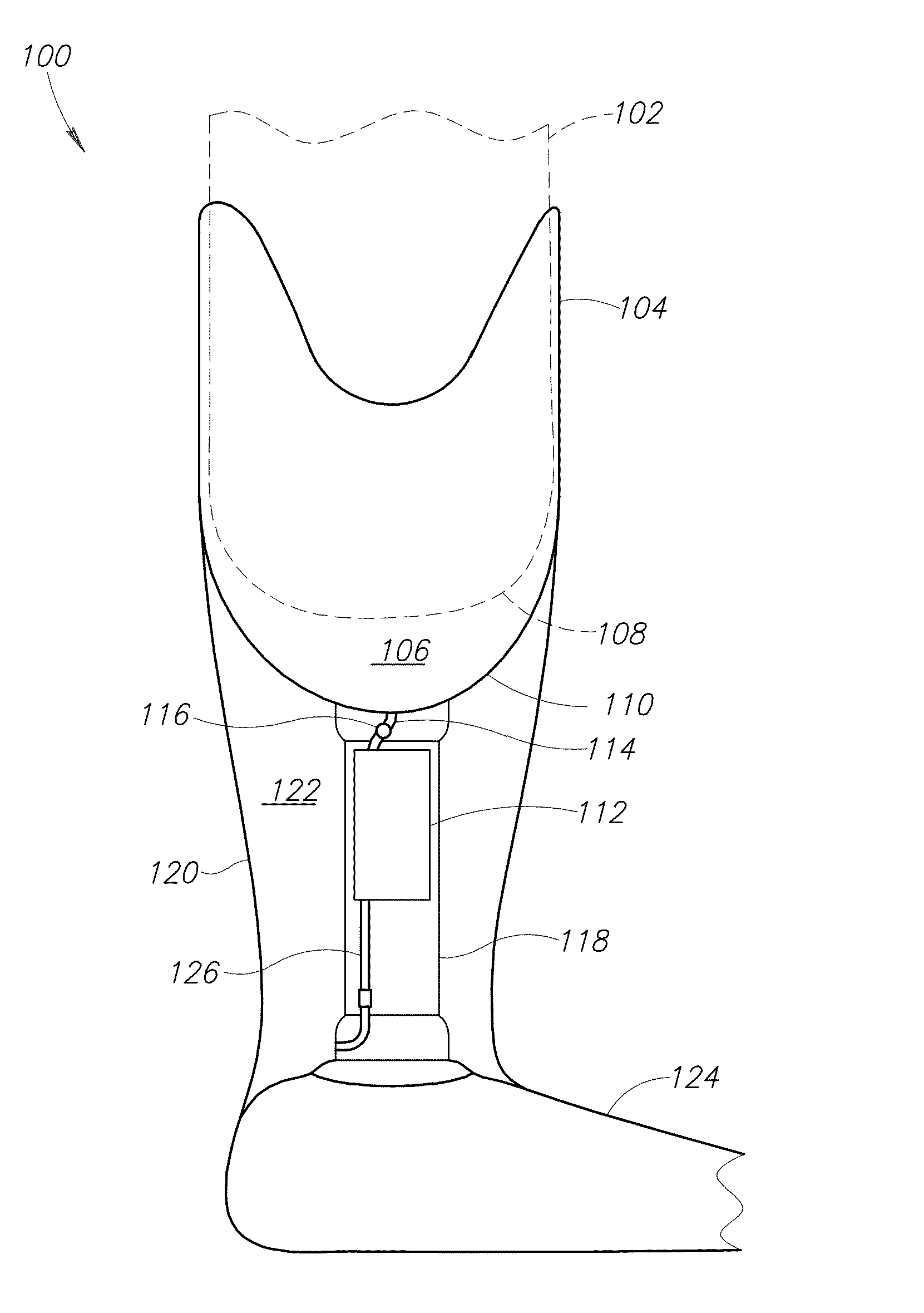
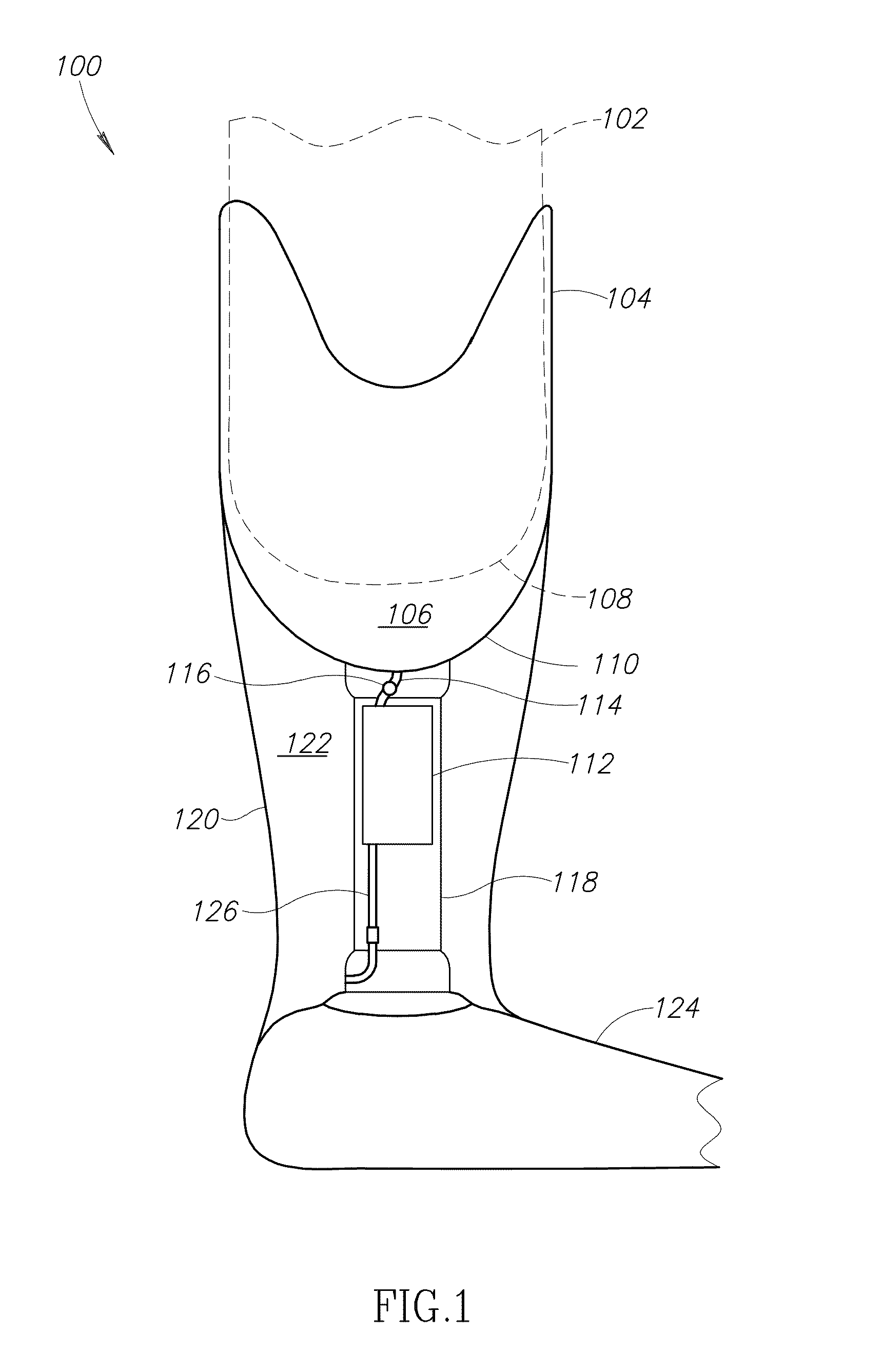
[0029]This disclosure, in general, describes a new and improved vacuum pump system that provides enhanced suspension and, in turn, a more effective and efficient prosthetic limb application. The pump system may advantageously provide an amputee with a safer and more comfortable fitting prosthesis that may have better proprioceptive control and feel as though the prosthesis is an extension of the wearer's own body.

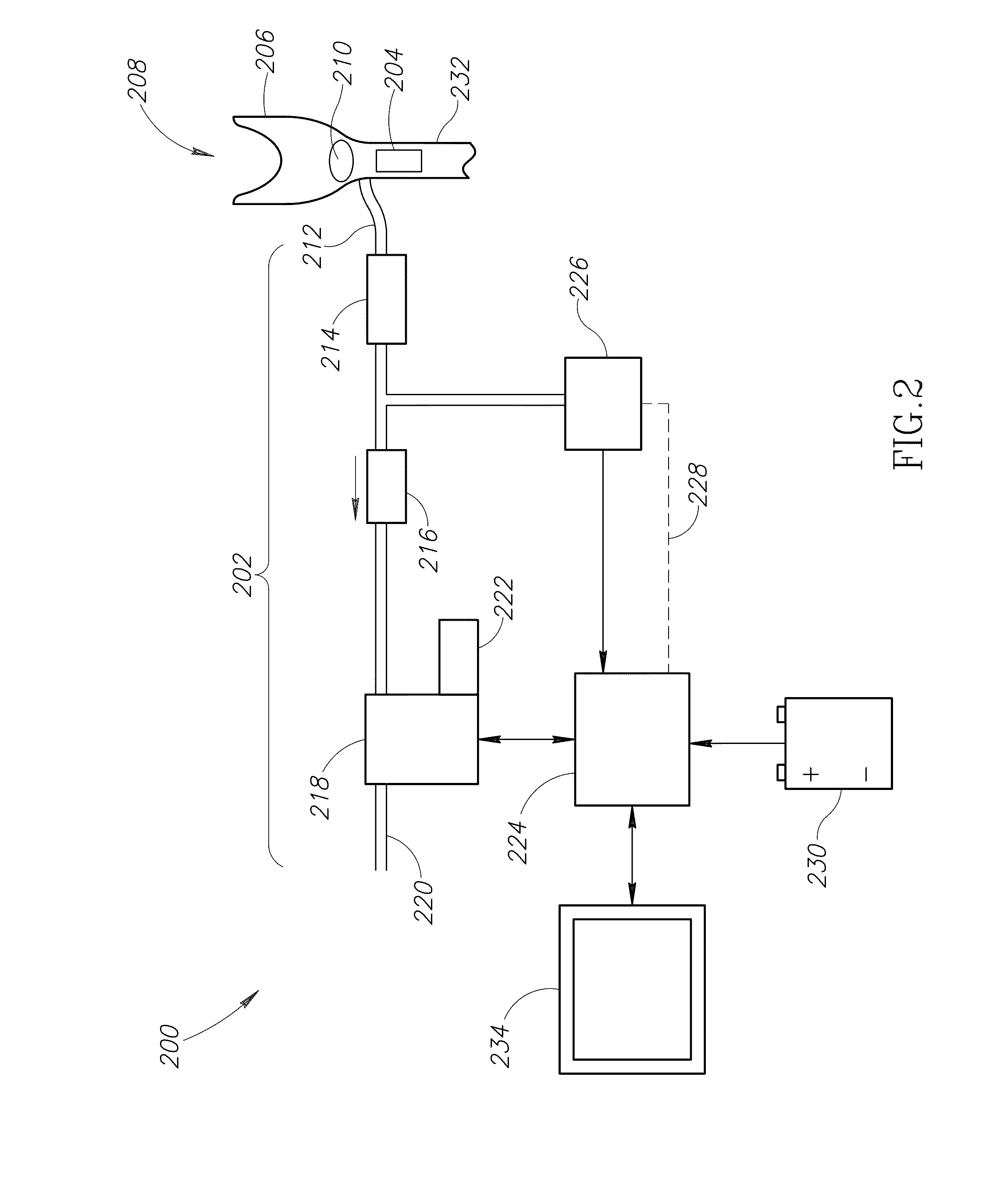
[0030]In one embodiment, a prosthesis integrates a socket, circuit, vacuum pump system, pylon, and power means while incorporating acoustic dampening and data collection capabilities. The processed data may permit a better fit of the prosthesis, for example tailored for each individual wearer. Further, the pump system includes a means for actively altering a vacuum pressure, in which such alterations may be initiated by the wearer, a prosthetist, a control system corresponding to environmental changes, or any combination thereof. Preferably, the pump system is sufficiently ...


PUM


Abstract

A vacuum pump system for a prosthesis includes an enhanced suspension mechanism and incorporates a vacuum pump system, an adaptor assembly, circuitry, and a power source. A virtually air-tight seal between a residual limb and a socket of the prosthesis allows a vacuum fit to be generated by the pump system. The pump system may be controlled with various circuits and processors receiving instructions from a software program. The pump system may be located within a pylon, but yet remain vibrationally and acoustically de-coupled from the pylon.

Description

PRIORITY CLAIM[0001]This application is a continuation-in part of U.S. patent application Ser. No. 12 / 776,300 filed on May 7, 2010, which is a continuation-in-part of U.S. patent application Ser. No. 12 / 440,581 filed on Mar. 9, 2009, which claims priority to International Patent Application No. PCT / U507 / 19723 filed on Sep. 11, 2007, which claims priority to U.S. Provisional Patent Application No. 60 / 843,969 filed on Sep. 12, 2006, wherein the subject matter of each is incorporated herein by reference in its entirety.FIELD OF THE INVENTION[0002]The present invention relates to a prosthetic pump system, and more specifically to a prosthetic pump system having a pylon coupled to an adaptor, the pylin configured to receive the pump system, which in turn is in fluid communication with a socket for adjusting a suspension of the prosthesis.BACKGROUND[0003]The field of prosthetics, in general, has made great advancements in improving performance on multiple levels for amputees and congenita...

Claims


Application Information

Patent Timeline
IPC IPC(8): A61F2/80
CPCA61F2/50A61F2/68A61F2/80A61F2002/701A61F2002/704A61F2002/802A61F2002/742A61F2002/7655A61F2002/766A61F2002/7665A61F2002/769A61F2002/705A61F2/70A61F2/742
Inventor MARTIN, JAMES JAYBUTEL, TYLERMARKMILLER, MICHAELKOZLOWSKI, MATTBOONE, DAVID
Owner ORTHOCARE INNOVATIONS
Why Eureka
Try Eureka