Above-knee prosthesis with variable resistance knee joint

a knee joint and variable resistance technology, applied in the field of above-knee prosthesis, can solve the problems of inability to allow users to ascend and descend stairs, inability to control the knee movement and no known device that prevents the giving way of artificial knee joints is capable of controlling the movement of the knee at any bending angl

Inactive Publication Date: 2005-01-20
HIKICHI YUICHI
View PDF5 Cites 51 Cited by
  • Summary
  • Abstract
  • Description
  • Claims
  • Application Information

AI Technical Summary

Benefits of technology

[0009] The user of this novel above-knee prosthesis can decrease the resistance of flexion or extension of the artificial knee joint by moving his or her thigh stump in an anterior direction until the knee joint rotates freely. Conversely, the user can increase the resistance of bending the knee joint, whether during flexion or extension, by moving the thigh stump in a posterior direction until the knee joint, ultimately, locks. The user is thus able to control the resistance in the artificial knee joint mechanically, without the use of electronic sensors, and without being fitted with a specialized socket that receives the thigh stump.
[0010] The anterior-posterior (AP) movement of the thigh stump is communicated to a hydraulic valve that controls the rate of flow of hydraulic fluid to and away from a hydraulic cylinder with piston. The cylinder with piston affects the rate at which the knee joint flexes and extends when a given force is applied. The ability to increase or decrease the resistance of the bending of the knee joint is unaffected by the angle of the knee joint, and thus available to the user at any bending angle. By increasing the resistance of the knee joint until the knee joint locks, the above-knee prosthesis is prevented from giving way.
[0011] A knee joint of an subject invention provides the user with confidence against the knee joint giving way, or drop-off, during normal walking operations since the user has the ability to increase knee resistance, and lock the knee joint, at any time during the walking cycle, regardless of the point in the cycle or the angle at which the knee joint is bent. Using the hip joint extensor muscles of an amputated thigh stump, the wearer can ascend and descend slopes and stairs demonstrating a reciprocating gait. By selective contraction of the hip joint extensor and hip joint flexor muscles of the amputated thigh stump, the wearer controls knee lock, knee yielding, and free knee swing motions voluntarily.
[0012] Given the invention's simple structure and non-reliance on electronic controls, sensors and specialized sockets, the above-knee prosthesis of the subject invention can be manufactured and provided to consumers at a relative low cost.

Problems solved by technology

However, none of the known devices that have been used to prevent the giving way of artificial knee joints are capable of controlling knee movement at any bending angle.
Another limitation of known above-knee prostheses is their inability to allow the user to ascend and descend stairs and slopes using a reciprocating gait.
While suitable for descending stairs and slopes, these devices cannot enable a reciprocating gait when ascending stairs or slopes.
Such devices require a specialized socket to receive the thigh stump, adding to the system's complexity and overall cost.

Method used


Image

  • Above-knee prosthesis with variable resistance knee joint
  • Above-knee prosthesis with variable resistance knee joint
  • Above-knee prosthesis with variable resistance knee joint

Examples


embodiment 10

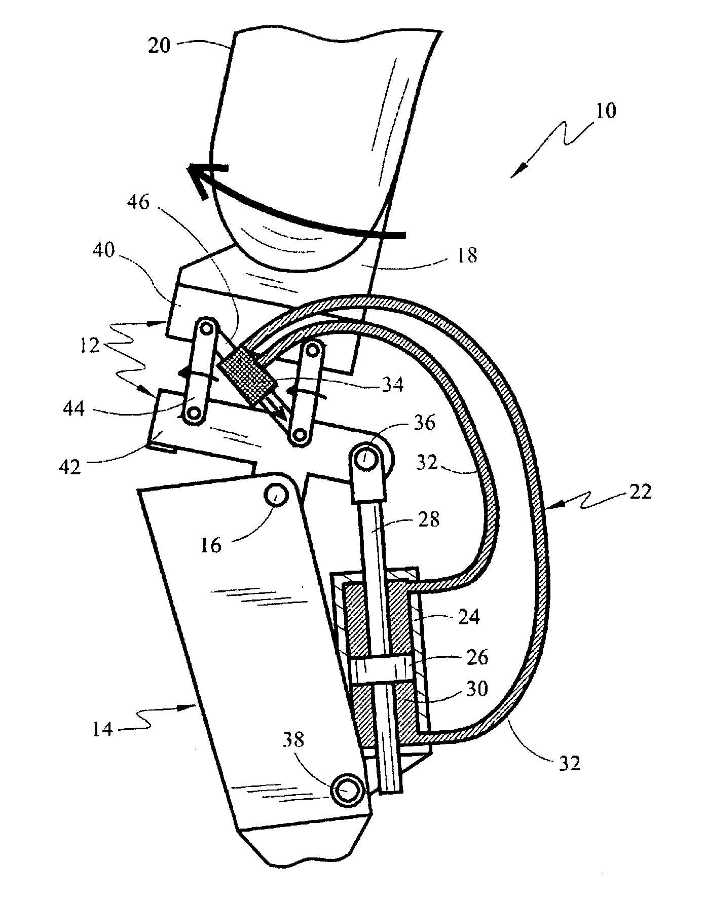
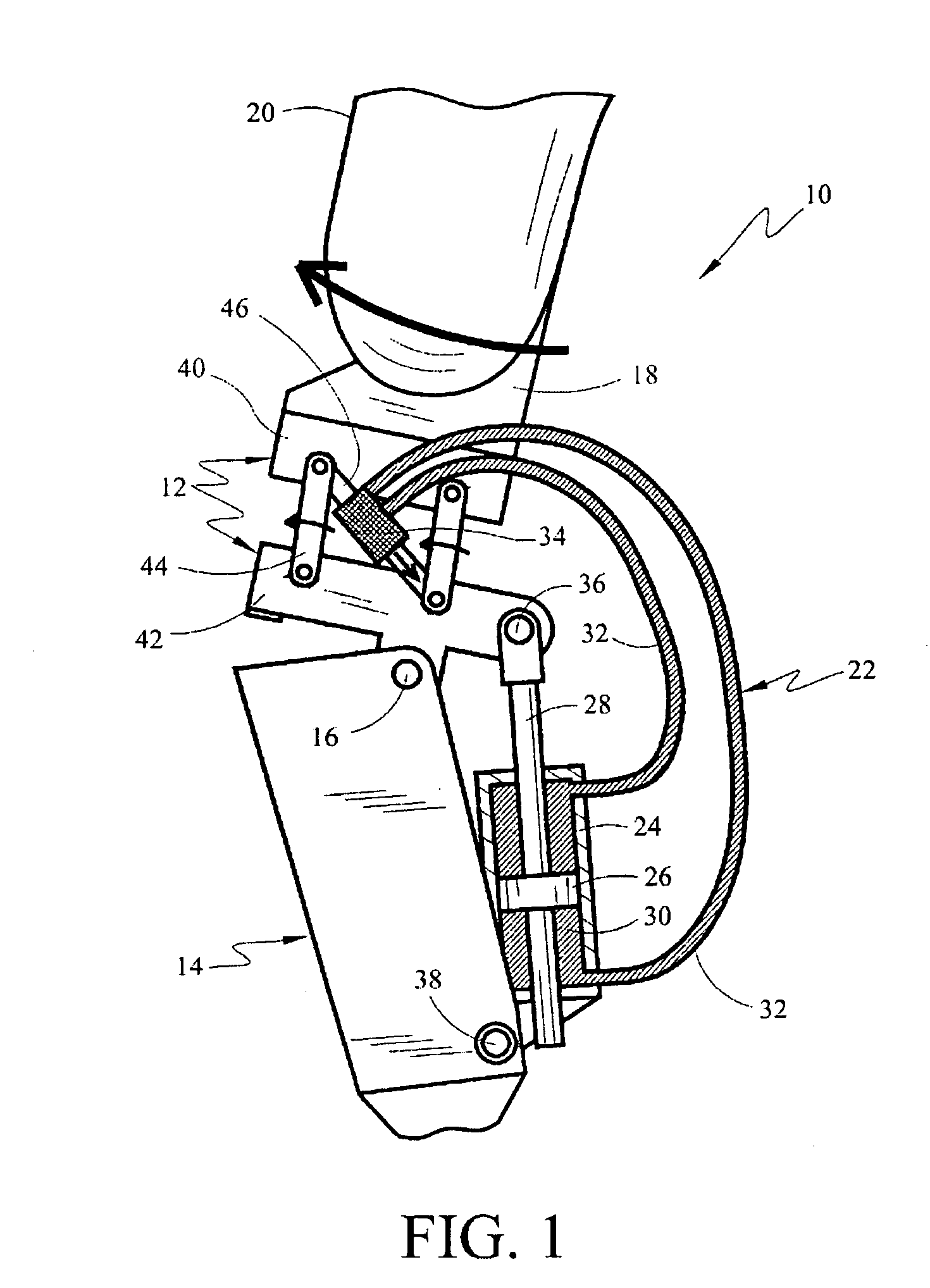
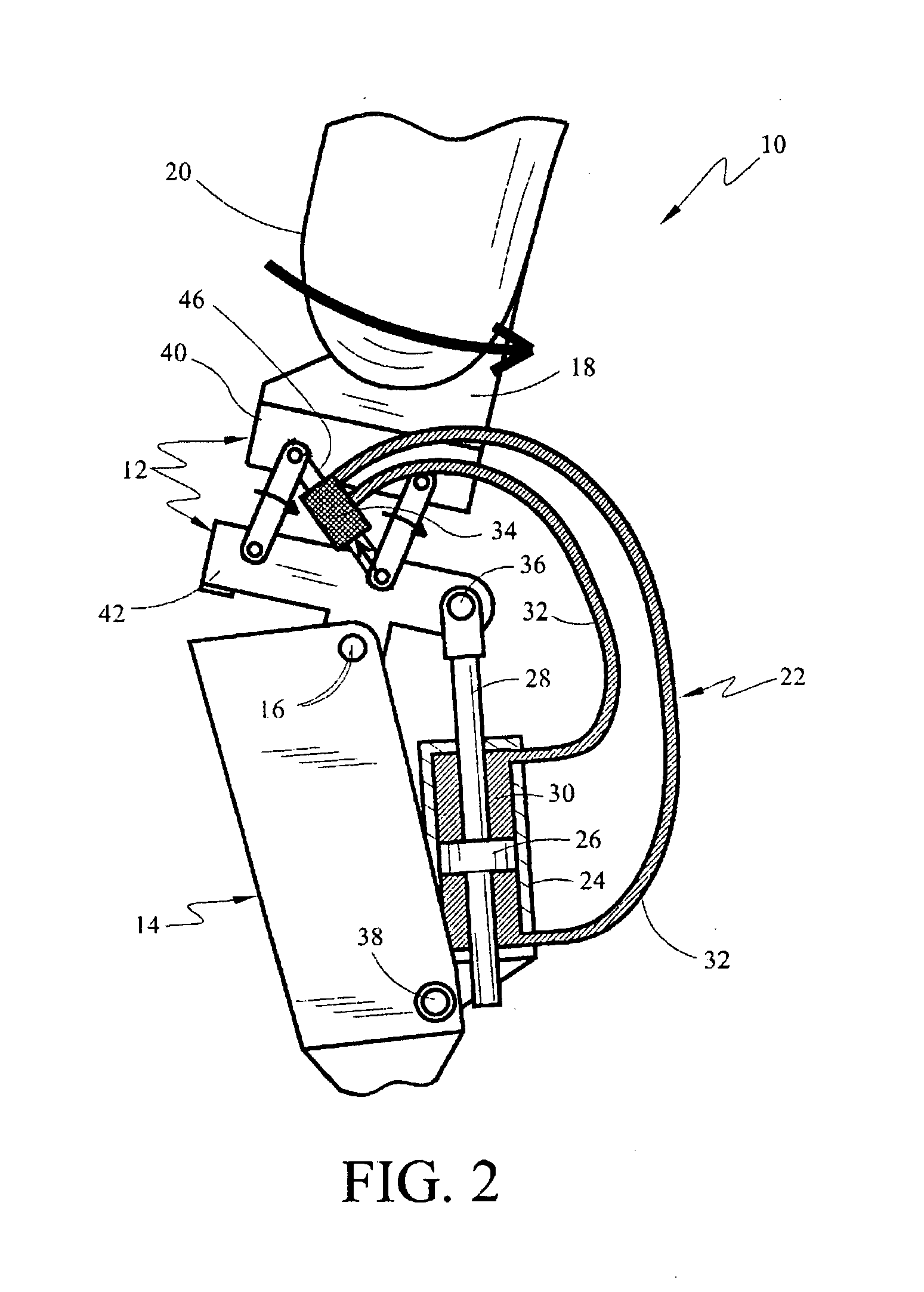
[0023] Illustrated in FIGS. 1 and 2 is a first preferred embodiment 10 of the above-knee prosthesis of the present invention, comprising a thigh frame assembly 12 that is rotatably connected to a leg frame assembly 14 by a knee pin 16, forming thereby, an artificial knee joint. A socket 18 is secured to the upper aspect of thigh frame assembly 12. Socket 18 may be hollow, with its upper aspect open to receive a femoral stump 20.

[0024] The degree of resistance of rotation of thigh frame assembly 12 relative to leg frame assembly 14 about knee pin 16 is controlled by a closed hydraulic system 22. Hydraulic system 22 comprises a hydraulic cylinder 24 housing a piston 26 attached to a piston rod 28 surrounded by a hydraulic fluid 30. System 22 further comprises tubing 32 that communicates the hydraulic fluid 30 between cylinder 24 and a hydraulic flow rate control value 34.

[0025] Closed hydraulic system 22 controls the resistance of bending of artificial knee 16 by interconnecting thig...

embodiment 50

[0029]FIGS. 3 and 4 depict a second preferred embodiment 50 of the above above-knee prosthesis of the present invention. Prosthesis 50 employs a different means for communicating the AP movement of the thigh stump to closed hydraulic system 22 and houses hydraulic system 22 partially within leg frame assembly 14.

[0030] Although partially hidden within leg assembly 14, hydraulic system 22 interconnects thigh assembly 12 and leg assembly 14 to provide resistance to knee bending in the same manner as hydraulic system 22 in above-knee prosthesis 10. The upper aspect of system 22 is rotatably fixed inside thigh assembly 12 through piston rod 28 and piston rod pin 36, and the lower aspect of hydraulic system 22 is rotatably fixed within leg frame assembly 14 through cylinder housing pin 38.

[0031] According to this embodiment, thigh frame assembly 12 is comprised of upper frame block 40, lower frame block 42, and a slide rail 52 that permits upper block 40 to slide relative to lower block...

embodiment 60

[0039] The details and manner of function of the sliding linkage assembly that serves to communicate the AP movement of the thigh stump to flow rate control valve 34 in preferred embodiment 60 are illustrated in FIGS. 8 and 9. FIG. 8 shows thigh frame assembly 12 of above-knee prosthesis 60, while FIG. 9 shows above-knee prosthesis 60 in cross-section.

[0040] Upper block 40 lies facing lower block 42 with slide rail 52 sandwiched between blocks 40 and 42 to facilitate the sliding of blocks 40 and 42 relative to one another. Dampers 54 are placed between lips formed on blocks 40 and 42 to dampen the abutment of these lips at the terminus of each slide.

[0041] As block 40 slides along slide rail 52 in an AP direction relative to block 42, a screw linkage 62 communicates this movement to a control screw 64 (shown in FIG. 9) causing control screw 64 to rotate. The rotating movement of control screw 64 is translated into displacement of linkage rod 46 that operates control valve 34. Depen...


PUM


Abstract

An above-knee prosthesis that allows the user to control the resistance of knee flexion or extension, and to voluntary lock and release the knee joint, at any and all bending angles, comprising a thigh frame assembly that receives a thigh stump; a leg frame assembly with foot attached; a hinge interconnecting the thigh frame and leg frame assemblies to form an artificial knee joint; a closed hydraulic system further interconnecting the thigh frame and leg frame assemblies to provide resistance to the bending of said artificial knee joint, a means to vary the resistance provided by said closed hydraulic system, and a means to translate the AP movement of said thigh stump into the degree of resistance provided by said closed hydraulic system. In its preferred embodiments, the AP movement of the thigh stump is communicated by means of a linkage, sliding or screw assembly, to a flow rate control valve. The flow rate control valve varies the amount of the resistance provided by the closed hydraulic system controlling, thereby, the amount of resistance within the artificial knee. Pressing the thigh stump backwards within the thigh frame assembly increases the resistance within the hydraulic system and slows knee bending until the knee locks. Pressing the thigh stump forward decreases the hydraulic resistive force and allows the artificial knee joint to yield to outside forces, such as gravity and / or stump thrust, until the prosthesis rotates freely about the knee hinge. The above-knee prosthetic prevents the knee joint from giving way, promotes a balanced stance, and facilitates a near normal reciprocating gate while ascending and descending stairs and slopes.

Description

CROSS-REFERENCE TO RELATED PATENT APPLICATIONS [0001] This application claims the benefit of Japanese Patent Application No. 2003-275716 filed Jul. 17, 2003, by the same inventor. STATEMENT REGARDING FEDERALLY SPONSORED RESEARCH OR DEVELOPMENT [0002] The subject invention is not the result of or in any way related to a federally sponsored research or development. TECHNICAL FIELD [0003] The invention relates to a knee joint for an above-knee prosthesis. More particularly, this invention describes a hydraulically controlled knee-joint for an above-knee prosthesis that allows the user to control the resistance of knee flexion and extension at all bending angles. BACKGROUND ART [0004] Artificial legs having knee joints, commonly referred to as above-knee prosthesis, are well known and understood. A variety of such prosthetic devices have been described in the available literature and many styles and types are commercially available. [0005] Preventing the giving way of the knee when in s...

Claims


Application Information

Patent Timeline
Patent Type & Authority Applications(United States)
IPC IPC(8): A61F2/50A61F2/64A61F2/68A61F2/70A61F2/74A61F2/76
CPCA61F2/64A61F2/68A61F2002/5032A61F2002/5033A61F2002/7625A61F2002/704A61F2002/748A61F2002/7605A61F2002/5039A61F2/748
Inventor HIKICHI, YUICHI
Owner HIKICHI YUICHI
Why Eureka
Try Eureka