Above-knee prosthesis with variable resistance knee joint
a knee joint and variable resistance technology, applied in the field of above-knee prosthesis, can solve the problems of inability to allow users to ascend and descend stairs, inability to control the knee movement and no known device that prevents the giving way of artificial knee joints is capable of controlling the movement of the knee at any bending angl
- Summary
- Abstract
- Description
- Claims
- Application Information
AI Technical Summary
Benefits of technology
Problems solved by technology
Method used
Image
Examples
embodiment 10
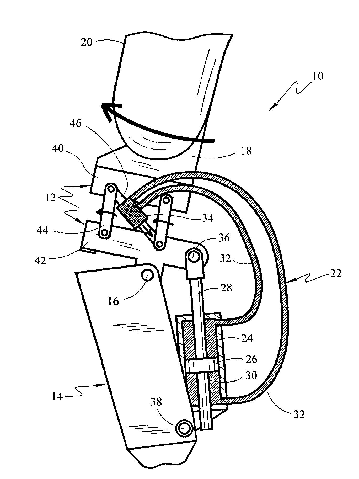
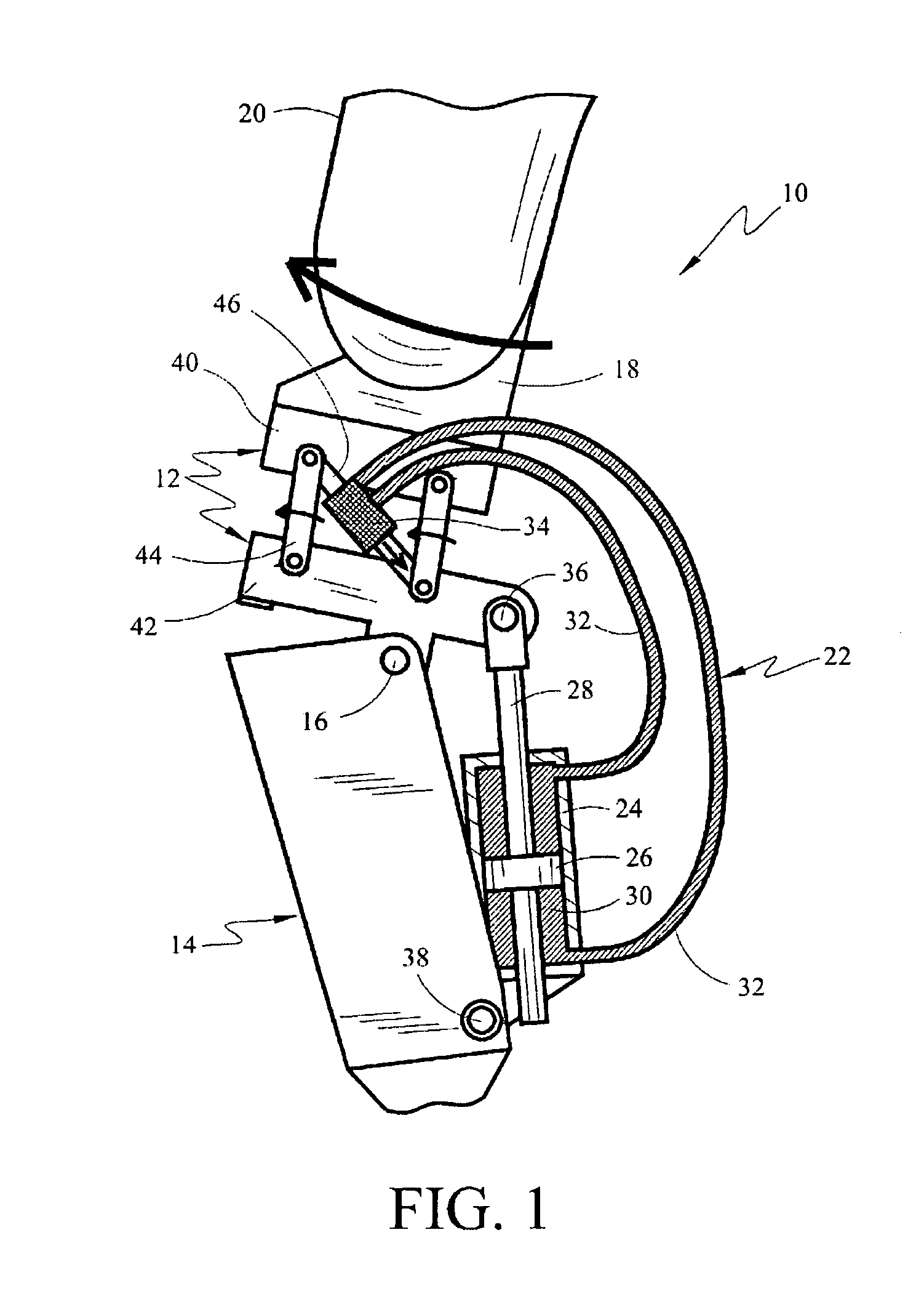
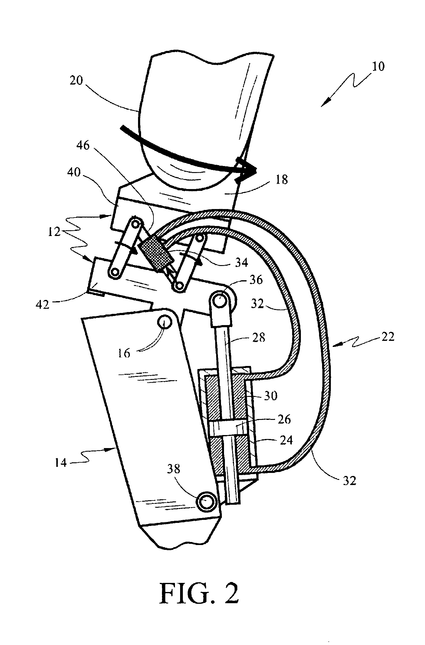
[0023]Illustrated in FIGS. 1 and 2 is a first preferred embodiment 10 of the above-knee prosthesis of the present invention, comprising a thigh frame assembly 12 that is rotatably connected to a leg frame assembly 14 by a knee pin 16, forming thereby, an artificial knee joint. A socket 18 is secured to the upper aspect of thigh frame assembly 12. Socket 18 may be hollow, with its upper aspect open to receive a femoral stump 20.
[0024]The degree of resistance of rotation of thigh frame assembly 12 relative to leg frame assembly 14 about knee pin 16 is controlled by a closed hydraulic system 22. Hydraulic system 22 comprises a hydraulic cylinder 24 housing a piston 26 attached to a piston rod 28 surrounded by a hydraulic fluid 30. System 22 further comprises tubing 32 that communicates the hydraulic fluid 30 between cylinder 24 and a hydraulic flow rate control value 34.
[0025]Closed hydraulic system 22 controls the resistance of bending of artificial knee 16 by interconnecting thigh as...
embodiment 50
[0029]FIGS. 3 and 4 depict a second preferred embodiment 50 of the above above-knee prosthesis of the present invention. Prosthesis 50 employs a different means for communicating the AP movement of the thigh stump to closed hydraulic system 22 and houses hydraulic system 22 partially within leg frame assembly 14.
[0030]Although partially hidden within leg assembly 14, hydraulic system 22 interconnects thigh assembly 12 and leg assembly 14 to provide resistance to knee bending in the same manner as hydraulic system 22 in above-knee prosthesis 10. The upper aspect of system 22 is rotatably fixed inside thigh assembly 12 through piston rod 28 and piston rod pin 36, and the lower aspect of hydraulic system 22 is rotatably fixed within leg frame assembly 14 through cylinder housing pin 38.
[0031]According to this embodiment, thigh frame assembly 12 is comprised of upper frame block 40, lower frame block 42, and a slide rail 52 that permits upper block 40 to slide relative to lower block 42...
embodiment 60
[0039]The details and manner of function of the sliding linkage assembly that serves to communicate the AP movement of the thigh stump to flow rate control valve 34 in preferred embodiment 60 are illustrated in FIGS. 8 and 9. FIG. 8 shows thigh frame assembly 12 of above-knee prosthesis 60, while FIG. 9 shows above-knee prosthesis 60 in cross-section.
[0040]Upper block 40 lies facing lower block 42 with slide rail 52 sandwiched between blocks 40 and 42 to facilitate the sliding of blocks 40 and 42 relative to one another. Dampers 54 are placed between lips formed on blocks 40 and 42 to dampen the abutment of these lips at the terminus of each slide.
[0041]As block 40 slides along slide rail 52 in an AP direction relative to block 42, a screw linkage 62 communicates this movement to a control screw 64 (shown in FIG. 9) causing control screw 64 to rotate. The rotating movement of control screw 64 is translated into displacement of linkage rod 46 that operates control valve 34. Depending...
PUM
 Abstract
Description
Claims
Application Information
 - R&D
- Intellectual Property
- Life Sciences
- Materials
- Tech Scout
- Unparalleled Data Quality
- Higher Quality Content
- 60% Fewer Hallucinations
Browse by: Latest US Patents, China's latest patents, Technical Efficacy Thesaurus, Application Domain, Technology Topic, Popular Technical Reports.
© 2025 PatSnap. All rights reserved.Legal|Privacy policy|Modern Slavery Act Transparency Statement|Sitemap|About US| Contact US: help@patsnap.com


