
System and method for laminating modules

a solar module and system technology, applied in the field of sandwiched body lamination, can solve the problems of shortening the lifetime of the membrane, affecting the reliability of the system, and affecting the lamination effect of the system, so as to improve the combination of convenience and utility.

Inactive Publication Date: 2012-11-01
3S SWISS SOLAR SYST
View PDF1 Cites 6 Cited by
  • Summary
  • Abstract
  • Description
  • Claims
  • Application Information

AI Technical Summary

Benefits of technology

[0007]In view of the foregoing disadvantages inherent in the prior arts, the general purpose of the present invention is to provide an improved combination of convenience and utility, to include the advantages of the prior art, and to overcome the drawbacks inherent in the prior art.
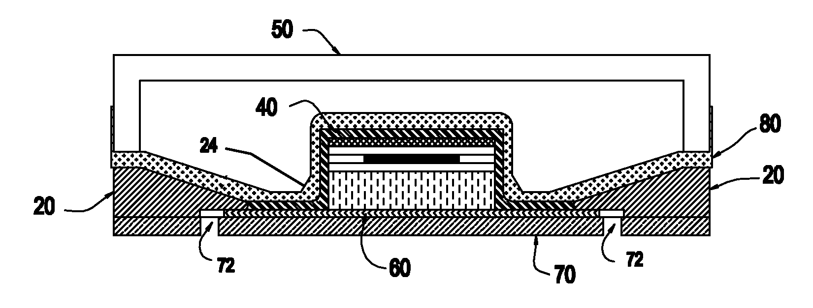
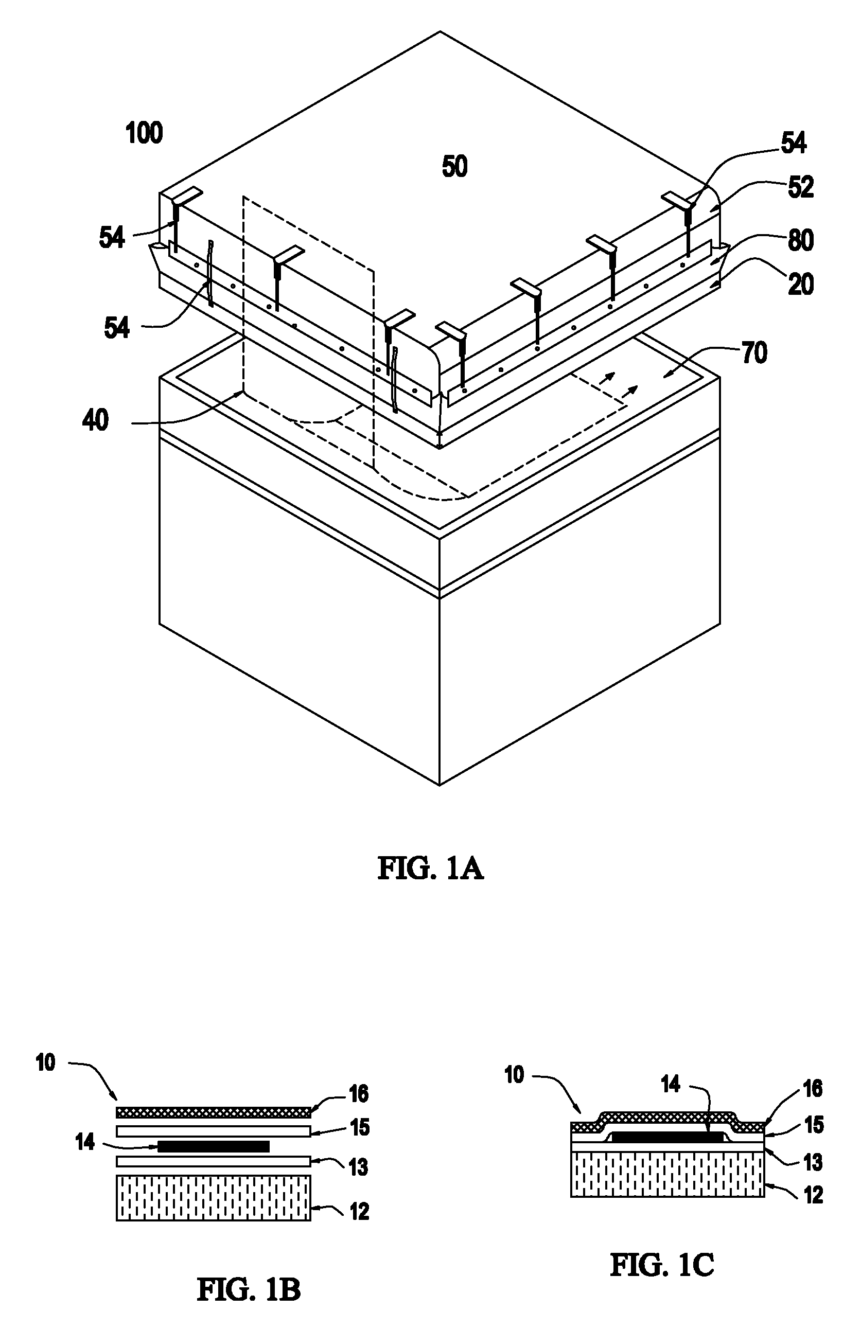
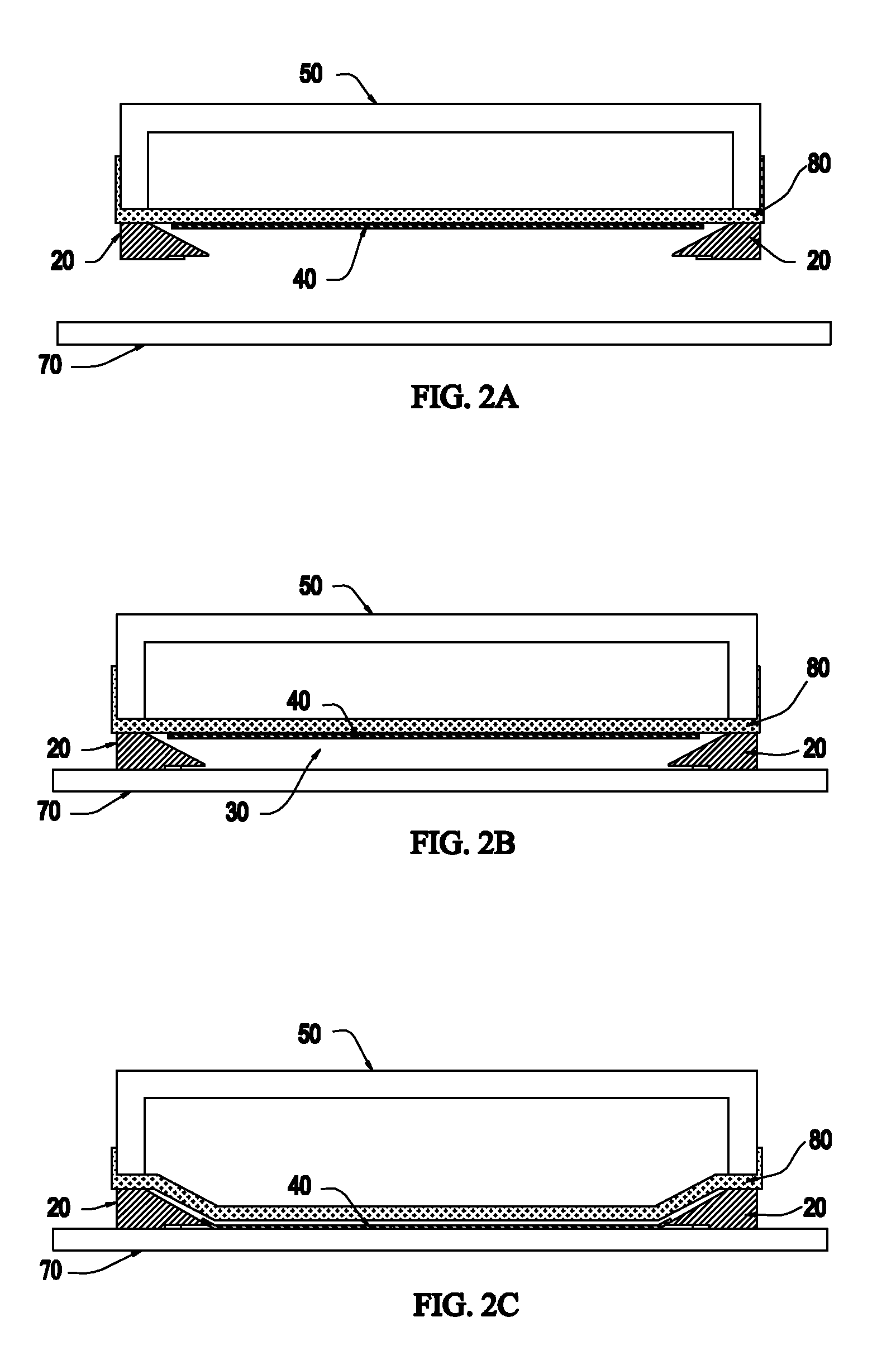
[0010]In another aspect, the present invention provides an improved and simplified system and method for laminating sandwiched bodies, lay-ups, and more particular for the lamination of solar module that may be mass produced inexpensively with the help of a stentering frame. The stentering frame in conjunction with the intermediate member is capable of preventing harmful gases from making contact with the membrane, that is, by allowing the harmful gases to be removed from the chamber without coming in contact with the membrane in order to prolong the lifetime of the membrane. The present invention incorporates within it simple structural indices for a simple, cost effective, secure, reliable, and environment friendly operation.

Problems solved by technology

Since the chamber is evacuated, the harmful gases flow off thru the conducts, but before doing so, the harmful gases come in contact with the membrane.
Contact of the harmful gases with the membrane affects the membrane in a negative manner, by accelerating thermo-oxidative aging, thus shortening lifetime of the membrane.
Many such systems are too complex for reliable operation and are incapable of protecting the expensive membrane from the harmful gases.
Also, the angle of the upper side of the stentering frame and a base is relatively large, which also impairs the lifetime of the membrane.
The features of the conventional laminating systems including aforecited prior art, disclose a complex design and bulky structural indices that hinder their performance.
However, no such system is available in the commercial market at the present time that is capable of preventing harmful gases from making contact with the membrane, that is, by allowing the harmful gases to be removed from the chamber without coming in contact with the membrane, in order to prolong the lifetime of the membrane.

Method used


Image

  • System and method for laminating modules
  • System and method for laminating modules
  • System and method for laminating modules

Examples


Embodiment Construction

[0032]The exemplary embodiments described here in detail for illustrative purposes are subject to many variations and structure and design. It should be emphasized, however that the present invention is not limited to a particular system and methods for laminating sandwiched bodies, lay-up, solar module, as shown and described. Rather, the principles of the present invention may be used with a variety of lamination configurations and structural arrangements. It is understood that various omissions, substitutions of equivalents are contemplated as circumstances may suggest or render expedient, but the present invention is intended to cover the application or implementation without departing from the spirit or scope of the claims.

[0033]In the following detailed description, for purposes of explanation, numerous specific details are set forth in order to provide a thorough understanding of the present invention. It will be apparent, however, to one skilled in the art that the present i...


PUM

PropertyMeasurementUnit
angleaaaaaaaaaa
angleaaaaaaaaaa
angleaaaaaaaaaa

Abstract

A system and method for laminating a module. The system comprises a membrane adapted to apply a pressure on the module to press a plurality of layers of the module together, an intermediate member adapted to prevent gases set free during a lamination process from making contact with the membrane, and a base for retaining the module, wherein the membrane and the base are capable of forming a vacuum chamber.

Description

[0001]This application is a 35 U.S.C. 371 national-phase entry of PCT International application no. PCT / IB2010 / 050240 filed on Jan. 19, 2010 and published as WO2011 / 089473A2 on Jul. 28, 2011; the entirety of parent PCT International application no. PCT / IB2010 / 050240 is hereby expressly incorporated herein by reference, in its entirety and as to all its parts, for all intents and purposes, as if set forth identically in full herein.FIELD OF THE INVENTION[0002]The present invention relates generally to laminating of sandwiched bodies, and, more particularly to system and methods for lamination of solar modules in a simple, cost effective, secure, and environmental friendly manner.BACKGROUND OF THE INVENTION[0003]In laminating of sandwiched bodies, more particular in the lamination of lay-up of solar modules, multiple layers, including adhesive foil, are joined together under the influence of heat and pressure. During lamination, the adhesive foils undergo chemical changes. Amongst oth...

Claims


Application Information

Patent Timeline
Patent Type & Authority Applications(United States)
IPC IPC(8): B32B37/10B29C65/02
CPCB32B37/0046B32B37/10B32B37/1009B32B2037/1223B32B2309/10B32B2309/105B32B2457/12B30B5/02
Inventor POLO, ROMANLANGE, RONALDCHIMENTI, ALESSANDROSTREBEL, BEATZAHND, JUERG
Owner 3S SWISS SOLAR SYST
Learn More