
Anchorage system

a technology of anchorage system and lateral axis, which is applied in the direction of bulkheads/piles, structural elements, building components, etc., can solve the problems of premature fibre rupture of tendon, and high concentration of lateral

Active Publication Date: 2012-11-29
GEOTECH
View PDF56 Cites 10 Cited by
  • Summary
  • Abstract
  • Description
  • Claims
  • Application Information

AI Technical Summary

Benefits of technology

[0022]filling the anchor head casing with an adhesive medium, thereby once the adhe

Problems solved by technology

In the case of a tendon formed from composite material, this compressive action of the wedges onto the tendon induced by the housing of the wedges into the anchor block, produces high concentrations of lateral stresses, causing premature fibre rupture of the tendon.
Present anchorage systems using steel tendons have the disadvantage that they are susceptible to corrosion and, as such, anchorage system standards require the use of double corrosion protection systems encapsulating the steel strands, to ensure a serviceable design life.
Most FRP anchorage systems alter the physical properties of the tendons being used, this is disadvantageous because altering of the properties may cause corrosion of the tendons and they may not perform as expected.
Furthermore, in the case of bond type systems, the bond length required can be substantial, making it very difficult to work in areas where space is a premium.
In addition, because a lot of material is required for the long bond length, costs are increased.

Method used


Image

  • Anchorage system
  • Anchorage system
  • Anchorage system

Examples


Embodiment Construction

[0035]Embodiments of the anchorage system will now be described with reference to the accompanying drawings.

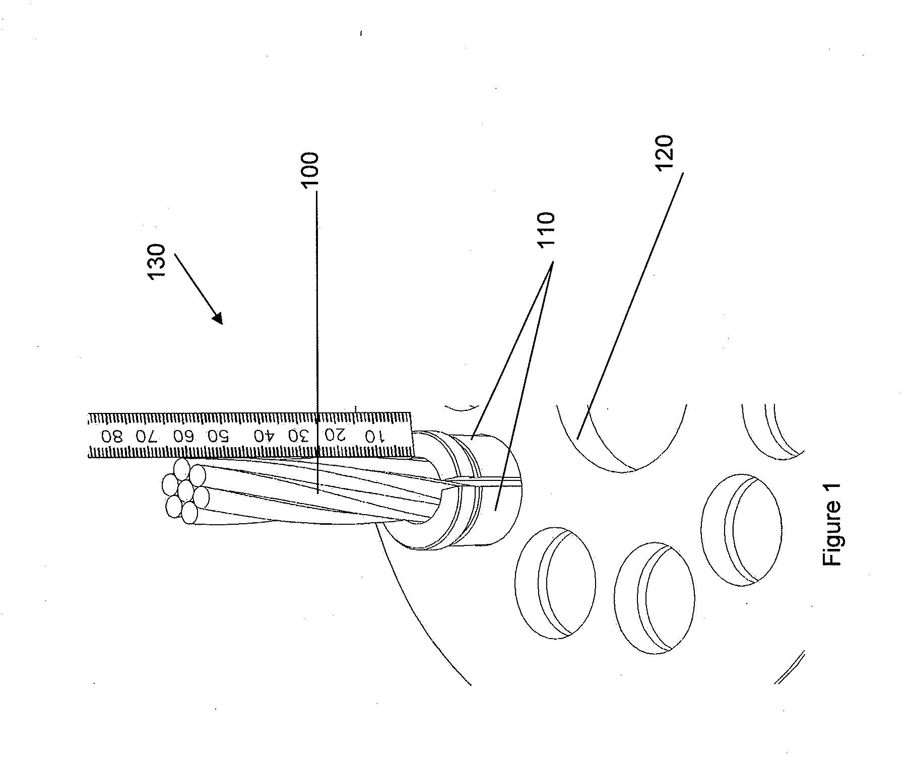
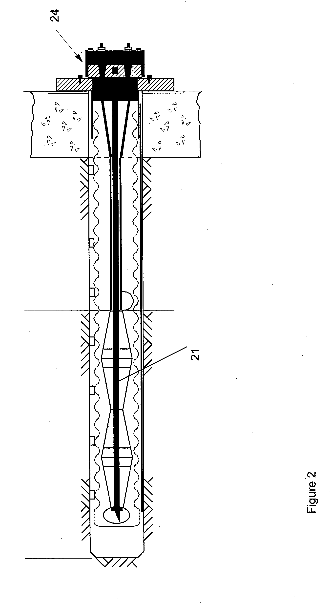
[0036]FIG. 2 shows a cross-section through an existing anchorage system in which pre-stressed tendons 21 are anchored in boreholes with anchor heads 24 at one end of each tendon 21. Failure can occur in the tendon 21 which can result in the anchor breaking. The failure may occur due to corrosion or other damage of the tendon and / or anchor head system or because the anchor head system is deficient in some way. The risk of failure in such an anchorage system may be significantly reduced if the tendon is replaced by a composite tendon and using anchor heads in accordance with the present invention. The wedge type anchorage system shown in FIG. 1 and the anchor head 24 in FIG. 2 can be replaced with the anchorage system in accordance with the present invention (an embodiment of which is shown in FIG. 3) in order to reduce the risk of failure.

[0037]In general, the present invention...


PUM

PropertyMeasurementUnit
Lengthaaaaaaaaaa
Strengthaaaaaaaaaa

Abstract

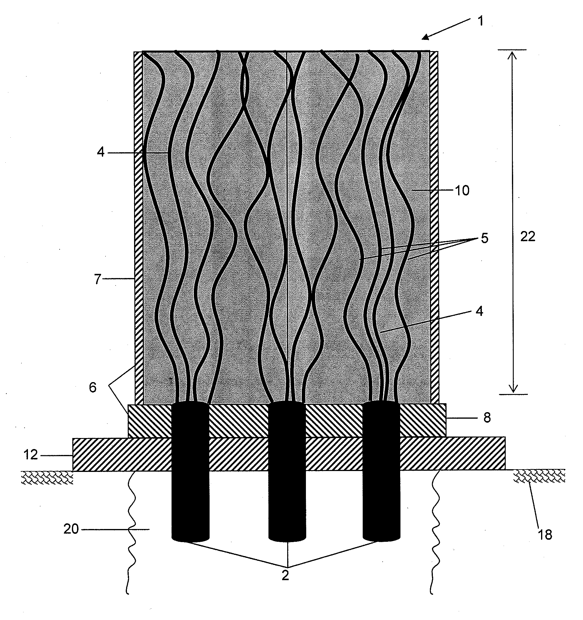
An anchorage system is provided which includes: a composite tendon (2) comprising an assembly of elongate elements (4, 5) held together and an anchor head including a casing (6). The individual elongate elements (4, 5) are separated from each other at one end extending into the anchor head, and the anchor head casing (6) is filled with an adhesive medium (10) to secure the separated elements (4, 5) in the casing (6). A method for installing an anchorage system is also provided including the steps of: inserting in a borehole at least one composite tendon (2) comprising an assembly of elongate elements (4, 5) held together; separating the individual elongate elements (4, 5) from each other over a pre-determined bonded anchor head length (22); placing an anchor head casing (6) around the separated elements (4, 5); and filling the anchor head casing (6) with an adhesive medium (10), whereby once the adhesive medium has set, the separated elements (4, 5) are securely fixed into the anchor head (6).

Description

FIELD OF THE INVENTION[0001]The present invention relates generally to anchorage systems and, in particular, to ground anchorage systems suitable for underground structures and above ground structures. It should be understood however that the invention is intended for broader application and use.BACKGROUND TO THE INVENTION[0002]Ground anchors are an integral construction technique for numerous civil engineering applications ranging from deep excavation support to resistance of structural uplift and overturning of superstructures. Ground anchorage systems can be designed to be temporary, such as for use in temporary wall support in deep excavations. They can also be designed to be permanent for use in structures, for example, bridges and dams.[0003]There are two significant types of anchorage systems which are in use; wedge type systems and bond type systems. Essentially, a wedge type anchorage system consists of steel wedges to grip single or multiple tendons in a tube with an inner...

Claims


Application Information

Patent Timeline
IPC IPC(8): E02D5/80E04B1/00
CPCE04C5/127E04C5/122E02D5/80
Inventor SENTRY, MATTHEW ROBERTCARRIGAN, LEONARD FRANCIS
Owner GEOTECH
Learn More