Gas sensor element and its manufacturing method, and gas sensor employing the gas sensor element

Active Publication Date: 2012-11-29
DENSO CORP
View PDF2 Cites 17 Cited by
  • Summary
  • Abstract
  • Description
  • Claims
  • Application Information

AI Technical Summary

Benefits of technology

[0033]Since the gas sensor element has the above-described advantages, the gas sensor in

Problems solved by technology

Therefore, when water drops included in the measurement gas come to adhere to the gas sensor element, a large thermal shock may be applied to the gas sensor element, thereby causing cracks to occur in the gas sensor element.
However, with the above technique, it may be difficult to evenly apply the slurry material on the outer surface of the main body of the gas sensor element.
Consequently, the thickness of the resul

Method used


Image

  • Gas sensor element and its manufacturing method, and gas sensor employing the gas sensor element
  • Gas sensor element and its manufacturing method, and gas sensor employing the gas sensor element
  • Gas sensor element and its manufacturing method, and gas sensor employing the gas sensor element

Examples


Example

First Embodiment

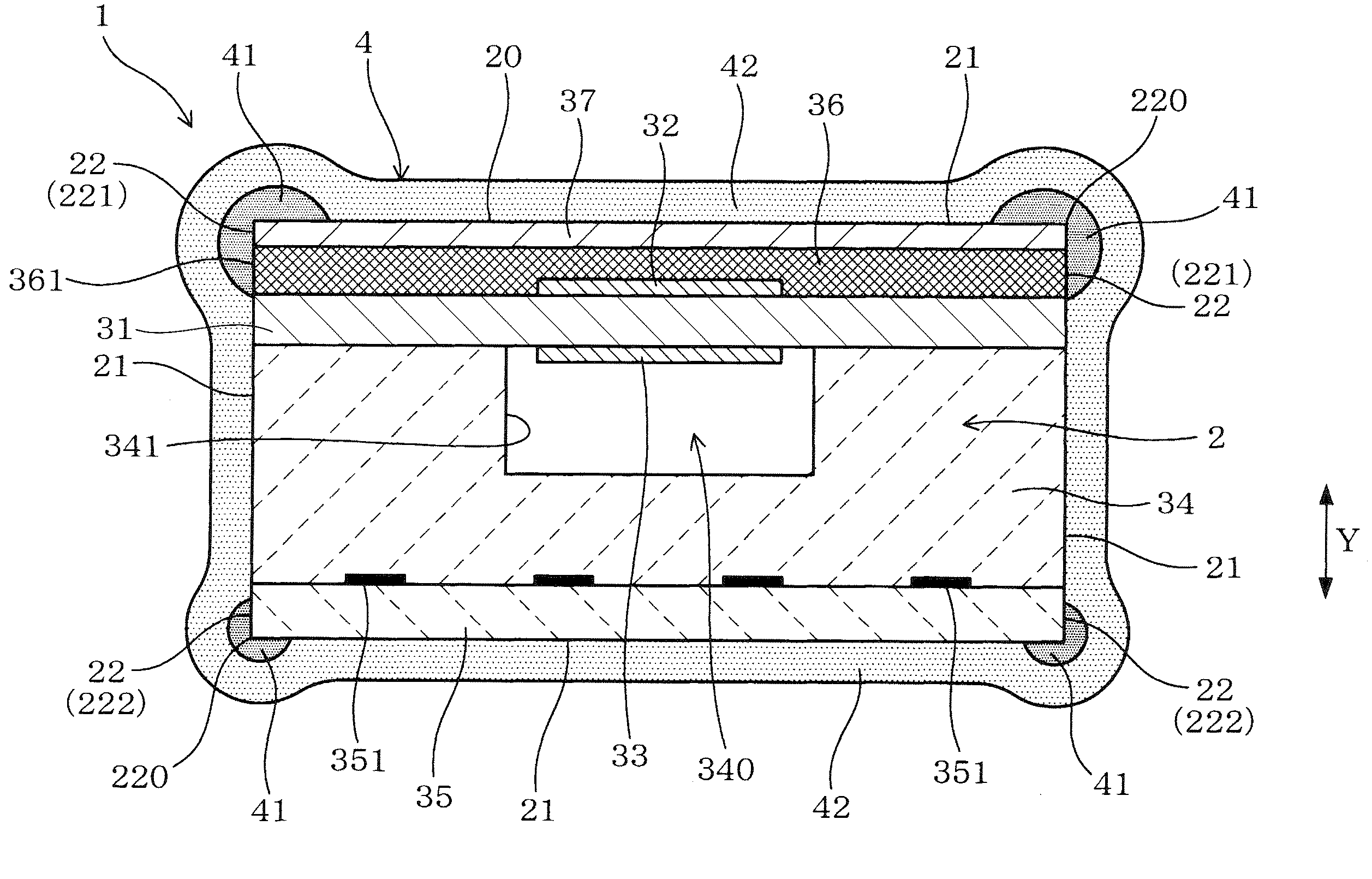
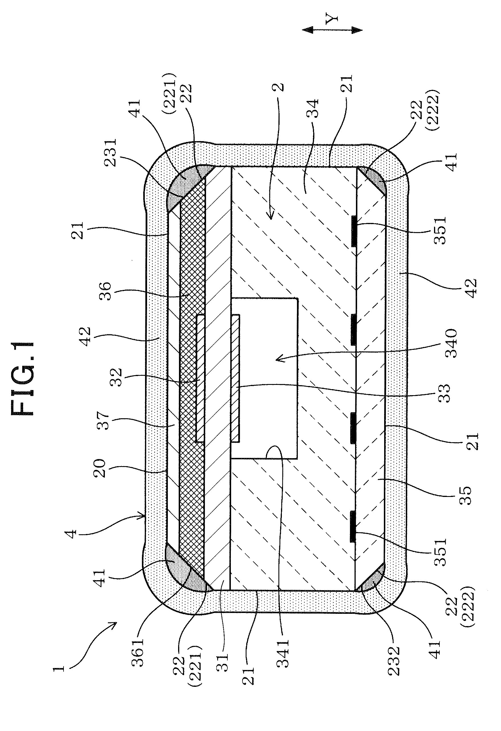
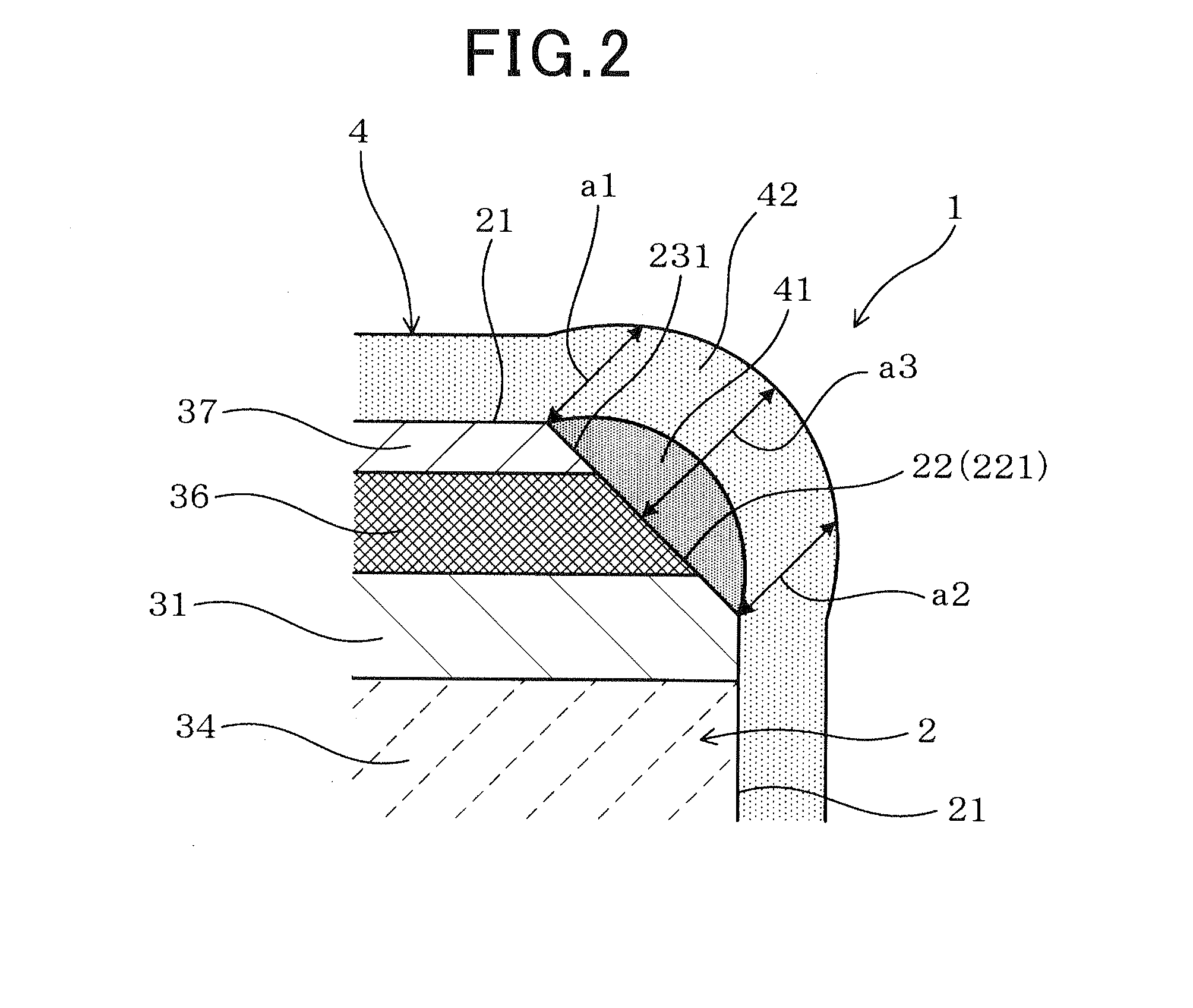
[0057]FIG. 1 illustrates the overall configuration of a gas sensor element 1 according to a first embodiment. FIG. 2 shows a corner portion of the gas sensor element 1.

[0058]As shown in FIGS. 1 and 2, the gas sensor element 1 has a main body 2 that includes a solid electrolyte body 31, a measurement electrode 32, a reference electrode 33, a heater layer 35, and a porous diffusion-resistant layer 36. The solid electrolyte body 31 has oxygen ion conductivity and a pair of first and second surfaces (i.e., the upper and lower surfaces in FIG. 1) that are opposite to each other in a lamination direction Y of the main body 2. The measurement electrode 32 is provided on the first surface of the solid electrolyte body 31 so as to be exposed to a measurement gas (i.e., a gas to be measured). The reference electrode 33 is provided on the second surface of the solid electrolyte body 31 so as to be exposed to a reference gas. The heater layer 35 is laminated on the same side of ...

Example

Second Embodiment

[0132]This embodiment illustrates a gas sensor element 1 which has a similar configuration to the gas sensor element 1 according to the first embodiment; accordingly, only the differences therebetween will be described hereinafter.

[0133]In the first embodiment, the inner protective layer 41 is formed on the main body 2 of the gas sensor element 1 so as to cover all the four corner portions 22 (i.e., the pair of first corner portions 221 and the pair of second corner portions 222) of the main body 2 (see FIG. 1).

[0134]In comparison, in the present embodiment, as shown in FIG. 6, the inner protective layer 41 is formed on the main body 2 of the gas sensor element 1 so as to cover only the first corner portions 221 of the main body 2. That is, in the present embodiment, each of the second corner portions 222 of the main body 2 has no inner protective layer 41 formed thereon.

[0135]With the above configuration of the gas sensor element 1 according to the present embodime...

Example

Third Embodiment

[0136]This embodiment illustrates a gas sensor element 1 which has a similar configuration to the gas sensor element 1 according to the first embodiment; accordingly, only the differences therebetween will be described hereinafter.

[0137]In the first embodiment, each of the first corner portions 221 of the main body 2 is chamfered to have the chamfer surface 231; each of the second corner portions 222 of the main body 2 is also chamfered to have the chamfer surface 232 (see FIG. 1).

[0138]In comparison, in the present embodiment, as shown in FIG. 7, none of the four corner portions 22 (i.e., the pair of first corner portions 221 and the pair of second corner portions 222) is chamfered to have a chamfer surface. Therefore, at each of the corner portions 22, corresponding two of the plane portions 21 of the main body 2 intersect each other at 90°.

[0139]Moreover, in the present embodiment, the protective layer 4 has an average thickness of 400 μm at each of the plane port...


PUM


Abstract

A gas sensor element includes a main body and a protective layer. The main body has four plane portions and four corner portions each of which is formed between one adjacent pair of the plane portions. The four corner portions include a pair of first corner portions that are formed on a porous diffusion-resistant layer side in a lamination direction of the main body and a pair of second corner portions that are formed on a heater layer side in the lamination direction. The protective layer is comprised of an inner protective layer that covers at least the first corner portions of the main body and an outer protective layer that covers the entire outer periphery of the main body and the inner protective layer. The protective layer has a larger average thickness at the first corner portions than at the plane portions of the main body.

Description

CROSS-REFERENCE TO RELATED APPLICATION[0001]This application is based on and claims priority from Japanese Patent Application No. 2011-118948, filed on May 27, 2011, the content of which is hereby incorporated by reference in its entirety into this application.BACKGROUND[0002]1. Technical Field[0003]The present invention relates to a gas sensor element for sensing the concentration of a specific component in a gas to be measured (to be simply referred to as a measurement gas hereinafter), a method of manufacturing the gas sensor element, and a gas sensor that employs the gas sensor element.[0004]2. Description of Related Art[0005]In exhaust systems of internal combustion engines of motor vehicles, there are generally provided gas sensors for sensing the concentration of a specific component (e.g., oxygen) in the exhaust gas (i.e., the measurement gas) from the engine.[0006]Moreover, the gas sensors generally have a gas sensor element embedded therein. The gas sensor element has a ma...

Claims


Application Information

Patent Timeline
IPC IPC(8): G01N7/00B05D3/02B05D5/00
CPCG01N27/4077G01N27/4072
Inventor MURAI, ATSUSHIYAMAMOTO, HIROYUKI
Owner DENSO CORP
Why Eureka
Try Eureka