Apparatus and method for function testing

Inactive Publication Date: 2005-03-24
GILMAN ENG & MFG
View PDF6 Cites 14 Cited by
  • Summary
  • Abstract
  • Description
  • Claims
  • Application Information

AI Technical Summary

Benefits of technology

[0006] The present invention relates to a method and device for function testing rack and pinion assemblies that provides low maintenance, high durability, and accurate measurements for the function testing of rack and pinion systems. One embodiment of the present invention utilizes a linear servo motor to provide the required force and motion for this system. The linear servo motor applies a constant resistive force to the rack. The resistive force applied to the rack is controlled by regulating the electrical current flowing to the linear motor. Application of a k

Problems solved by technology

Disadvantages of the hydraulic servos described above include, for example, the inherent leaks and housekeeping associated with hydraulic systems.
Hydraulic servo systems are very sensitive to contamination of the system itself.
The disadvantage of the ball screw actuators is that the i

Method used


Image

  • Apparatus and method for function testing
  • Apparatus and method for function testing
  • Apparatus and method for function testing

Examples


Embodiment Construction

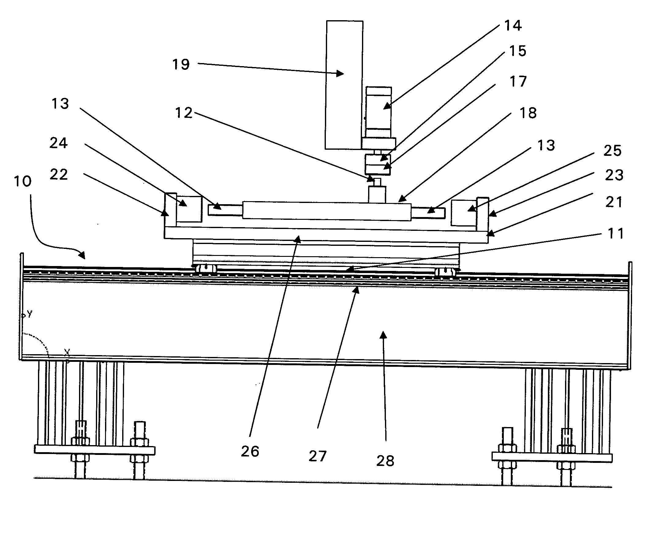
[0011] Given the disadvantages of the prior art, there is a need for a more efficient apparatus to function test various systems. One aspect of the present invention relates to the use of a linear servo motor. Another aspect concerns the use of a generally “U” shaped structure as an actuator. A preferred embodiment of the present invention involves the use of a linear servo motor and the generally “U” shaped structure to function test a rack and pinion assembly.

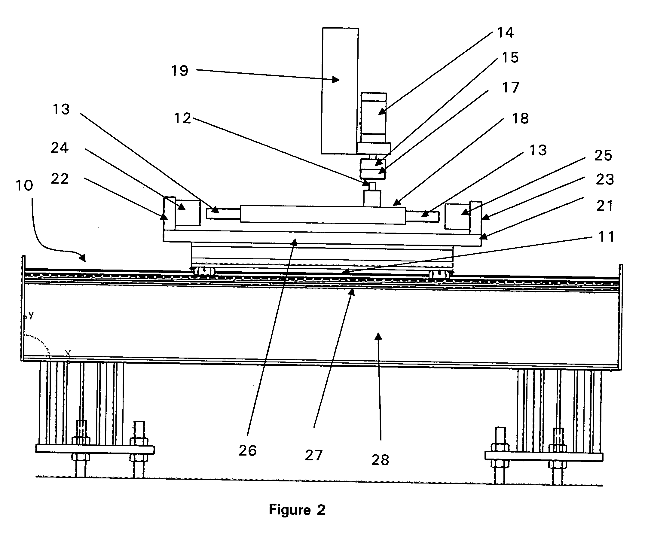
[0012] Referring to the preferred embodiment shown in FIG. 2, a function test station 10 in accordance with the principles of the present invention utilizes a generally “U” shaped structure 21 to provide the force to both ends of a rack 13 and a linear motor 11 to provide the resistive force to the rack 13. The linear motor 11 is used to apply the required forces. A pinion drive 14 is connected to a torque transducer 15. A pinion coupling 17 connects the pinion drive 14 via the torque transducer 15 to an input shaft 12 of an...


PUM


Abstract

An apparatus for function testing rack and pinion systems having a linear servo motor. A single actuator provides force to both ends of the rack and a linear motor to provide resistive force to the rack. The linear motor is used to apply the required forces. In a preferred embodiment, the actuator is a generally “U” shaped structure mounted onto a linear motor stage. A force transducer is placed at each end of the generally “U” shaped structure between the structure and the rack to monitor the force being applied to the rack.

Description

FIELD OF THE INVENTION [0001] The present invention relates generally to function testing. BACKGROUND OF THE INVENTION [0002] Rack and pinion gears or assemblies are used to convert rotation into linear motion. A common method to conduct a function test on rack and pinion assemblies utilizes two servo-controlled hydraulic cylinders pushing against each end of the rack as a separate servo motor rotates the pinion. Load cells between the hydraulic cylinder and the rack provide a feedback signal that is used by the servo controller to maintain a constant force against the rack. A torque transducer provides a feedback signal showing the torque required to turn the pinion. The motion and required drive torque of the pinion are compared against the force and position of the rack to verify the correct operation of the assembly. An alternative method employs, in place of the two hydraulic cylinders, two ball-screw driven actuators, or electric cylinders, that push springs against the opposi...

Claims


Application Information

Patent Timeline
IPC IPC(8): G01L3/26G01M13/02
CPCG01M13/021
Inventor TERPSTRA, PAUL D.
Owner GILMAN ENG & MFG
Why Eureka
Try Eureka