Exhaust gas sensor

Active Publication Date: 2006-03-02
YAMAHA MOTOR CO LTD
View PDF21 Cites 13 Cited by
  • Summary
  • Abstract
  • Description
  • Claims
  • Application Information

AI Technical Summary

Benefits of technology

[0008] An aspect of the present invention includes an exhaust gas sensor which prevents a detecting sens

Problems solved by technology

Thus, when water flows through the exhaust gas pipe towards the engine, the water may not reach the exhaust gas sensor.
Unfortunately, water can still reach the vicinity of the detecting part o

Method used


Image

  • Exhaust gas sensor
  • Exhaust gas sensor
  • Exhaust gas sensor

Examples


Embodiment Construction

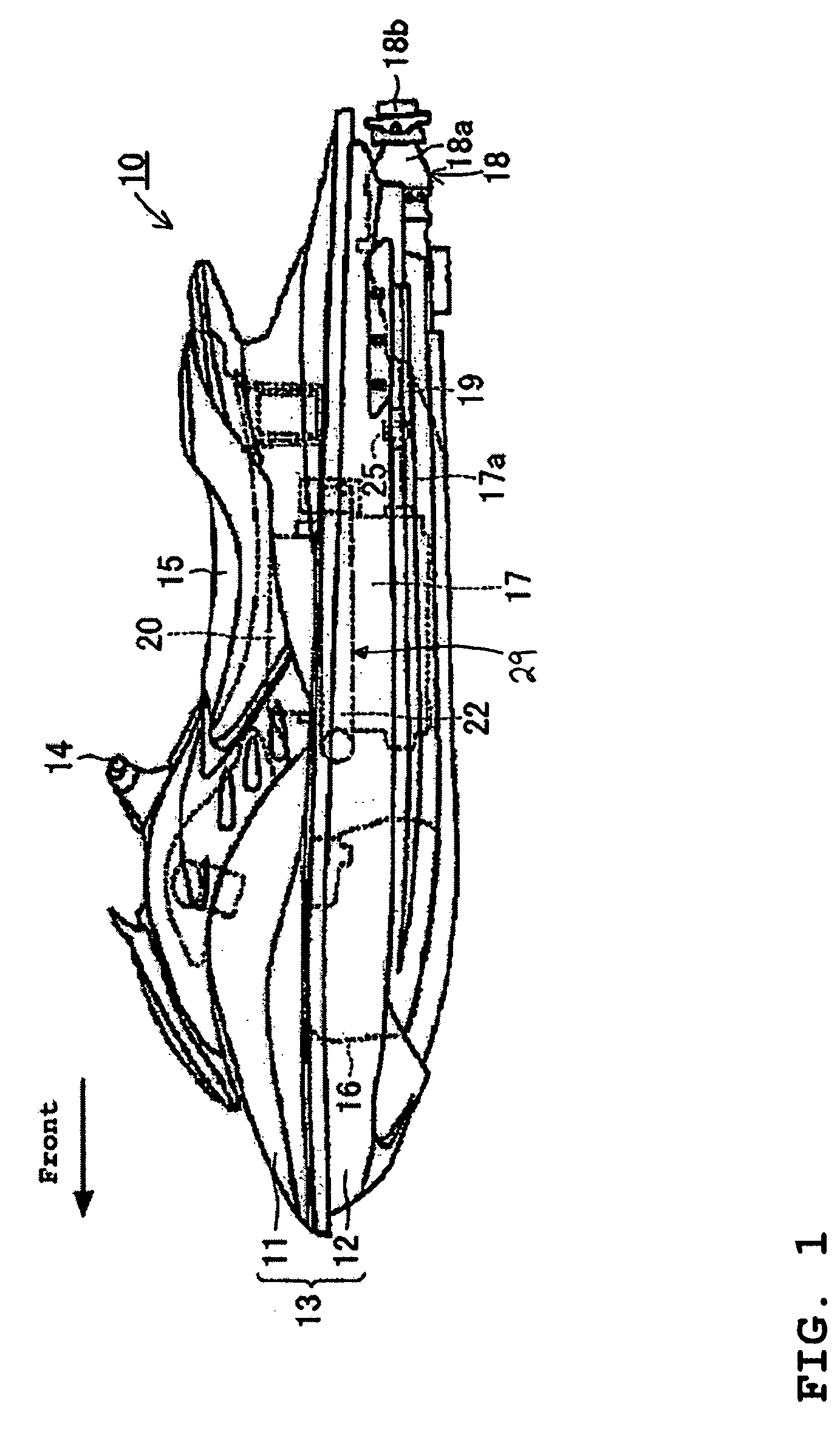
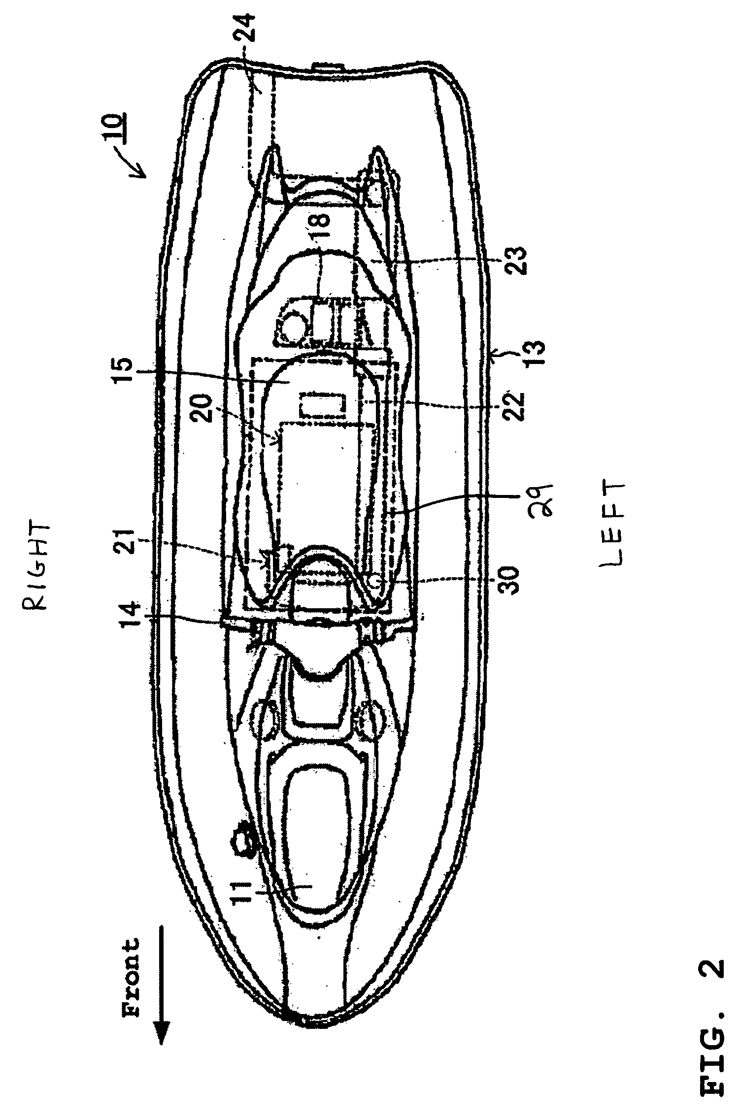
[0026] With reference to FIGS. 1 and 2, an overall configuration of a personal watercraft 10 and its engine 17 and exhaust system 29 is described below. The described exhaust system has particular utility for use with the personal watercraft, and thus, it is described in the context of personal watercraft. However, the exhaust system can also be applied to other types of vehicles, such as small jet boats and other vehicles that feature marine drives, automobiles, motorcycles, scooters, and the like, as well as industrial stationary engines, generators, and other engines, for example. The terms “upper,”“lower,”“top,”“bottom,”“left,”“right,” and the like may be used to describe the watercraft 10. These terms are used in reference to the illustrated embodiments and are from the perspective of a rider straddling a seat 15.

[0027] The watercraft 10 has a body 13 that includes upper hull section 11 and a lower hull section 12 (FIG. 1). The upper and lower hull sections 11, 12 cooperate to...


PUM


Abstract

An exhaust gas sensor inhibits a detecting part of an exhaust gas sensor from being exposed to water and has high detection accuracy and high durability. The exhaust gas sensor has a sensor body and a protective cover. The sensor body has an outer housing. The outer housing has a plurality of gas inlets. A gas detection element for detecting a component of the exhaust gas (e.g., oxygen) disposed within the outer housing. The protective cover has a cylindrical shape and has a plurality of protrusions at its opposing ends. The protrusions provide a tight fit with the outer housing. The protective cover is attached to the outer periphery of the outer housing without closing gas inlets formed through the outer cylinder by press-fitting the outer cylinder into the protective cover.

Description

PRIORITY INFORMATION [0001] The present application is based on and claims priority under 35 U.S.C. § 119(a-d) to Japanese Patent Application No. 2004-244612, filed on Aug. 25, 2004, the entire content of which is expressly incorporated by reference herein. BACKGROUND OF THE INVENTION [0002] 1. Field of the Invention [0003] The present invention relates to exhaust gas sensors and, more particularly, to exhaust gas sensors that are mounted to an exhaust conduit of an exhaust system. [0004] 2. Description of the Related Art [0005] Internal combustion engines typically power vehicles. Internal combustion engines output exhaust gases that contain combustion by-produces. These exhaust gases often pass through an exhaust system before being expelled from the vehicle. Detectors often measure the concentration of oxygen in the exhaust gases so that the air-fuel ratio of the air-fuel mixture can be controlled based on an output from the detector. Typically, a detector is provided in an exhau...

Claims


Application Information

Patent Timeline
IPC IPC(8): G01N27/26F01N13/00F01N99/00F02D45/00G01N27/409
CPCG01N27/4077
Inventor TSUKAHARA, KOJUOZAWA, SHIGEYUKINONAKA, ISAO
Owner YAMAHA MOTOR CO LTD
Why Eureka
Try Eureka