
Reaction turbine and hybrid impulse reaction turbine

Active Publication Date: 2013-04-25
HYBRID TURBINE GRP
View PDF9 Cites 12 Cited by
  • Summary
  • Abstract
  • Description
  • Claims
  • Application Information

AI Technical Summary

Benefits of technology

This patent describes a new type of turbine that combines an impulse component and a reaction component to achieve high efficiency, durability, and the ability to use a wide variety of fuels. The impulse turbine is smaller and operates at subsonic speeds, while the reaction turbine operates at supersonic speeds. The system can also incorporate ceramics and other advanced materials that cannot currently be used in conventional turbines. The design is simple and cheap to manufacture, and it is durable to operate in harsh environments. The system also eliminates surging problems and provides maximum shaft power. The impulse turbine which operates at low speed and minimizes impact damage is ideally matched to the high-speed nozzles at the perimeter of the disc. This results in minimal losses when turning supersonic flows.

Problems solved by technology

Most notably, inventors from da Vinci to de Laval to Pelton have all noted that for maximum water wheel, the fluid must (1) enter slowly and evenly, or else losses will occur before the power can be extracted, (2) proceed through smooth, gradual steps, or else the power will be lost to the surroundings instead of being harvested, and (3) exit at essentially no velocity, because any residual velocity results in kinetic energy that is outside of the machine and thus cannot be converted to useful power.
Unfortunately, applying the above general relationship of no residual energy in the exhaust requires that the exhaust velocity must equal the jet velocity.
Despite this inherent simplicity, the reaction turbine has never been successfully utilized for power generation.
The limitations follow from the basic design.
First, feeding in water is obviously difficult with limited machining capability.
Ideally, this progression should be smooth, but with a spinning mixture of liquid and gas, combined with exits that move relative to the gas (no internal partitions), the internal process is complicated indeed, leading to significant losses.
It is therefore not surprising that the Hero turbine produces no useful power.
Similar problems persist in more modern attempts.
Specifically, reaction turbines lack the delicate blades that limit conventional turbines.
The first problem with this relationship is that Sohre specifies a supersonic tip velocity, and shows the water jet at about half the tip radius.
This is simply not practical for multiple reasons: (1) water is not compressible, and therefore does not follow the laws of compressible flow that govern the gas phase—the gas and water components of the unit are therefore not compatible, (2) water will be subject to pump work, as described below, and (3) the amount of water in any practical two phase system is inadequate to form a useful jet—the losses would be excessive for a small diameter nozzle, but a large diameter nozzle would be inadequate to serve as a plug for the steam.
One problem is that the above general relationship states that any residual velocity decreases the efficiency.
Reaction turbines, however, produce no power from radial velocity—only tangential (or angular) velocity yields useful power.
The above simple relation v=r ω, however, says that such a rapid speed increase is simply not possible while maintaining the specified tangential flow equations.
Finally, progressing towards the axis reveals one last problem that is quite instructive: mass conservation.
The fundamental problem here is that compressible flows, such as air or steam at high velocity, have properties that limit the types of flow that are possible.
Therefore, Sohre's unit violates the above mass flow rate law: it is simply not physically possible for any given mass flow rate to satisfy the contradictory conditions in the Sohre geometry.
Unfortunately, the Fabris unit begins with a problem already cited by U.S. Pat. No. 4,336,039 (Sohre): limited exhaust nozzle arrangements.
Most of the disc is therefore wasted space.
Such an arrangement is simply not competitive on a mass and volume basis with conventional turbines.
Another problem with the Fabris unit is the inlet zone at the axis.
Like the Sohre unit without partitions, this zone is not partitioned, and therefore suffers from the unequal distribution problems that date back to Hero.
Furthermore, the Fabris unit also suffers from excessive efficiency losses due to high inlet velocities, as discussed more fully below.
However, the computer program that Fabris uses to calculate these effects has flaws.
The difficulty here is that Fabris has omitted crucial terms in the computational model: losses and the work done by the gas on the rotor in the tangential direction prior to the exit.
Because these terms decrease the exit velocity in the rotating case, the Fabris algorithm of mandated identical exit velocities invariably converges to the wrong solution.
Such large discrepancies are simply unacceptable in turbine work, where variations of even fractions of a percent are important.

Method used


Image

  • Reaction turbine and hybrid impulse reaction turbine
  • Reaction turbine and hybrid impulse reaction turbine
  • Reaction turbine and hybrid impulse reaction turbine

Examples


Embodiment Construction

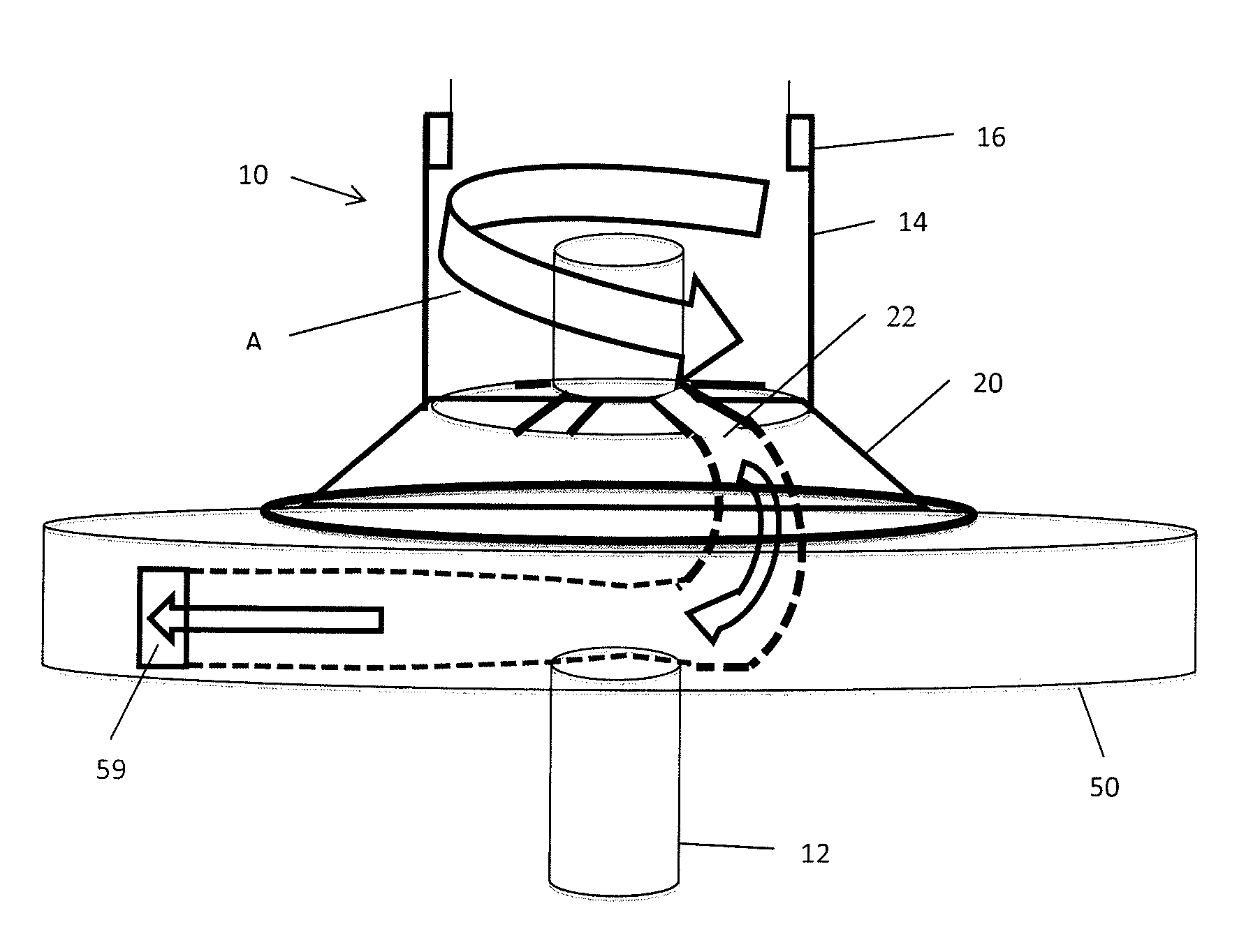
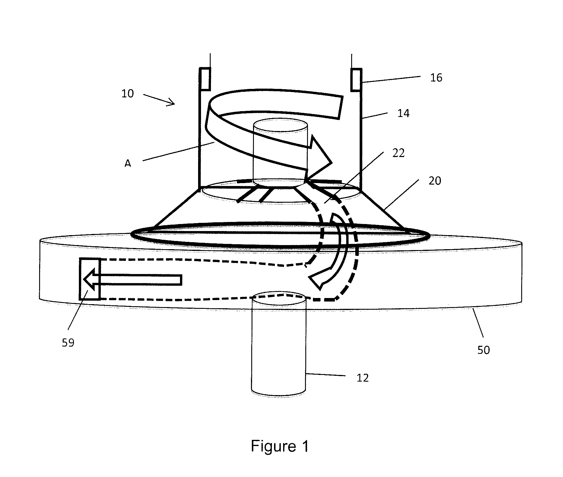
[0055]As seen in FIG. 1, the hybrid turbine 10 has a solid shaft 12 supporting all components and powered by the turbine components. An intake conduit 14 supplies fluid from any suitable source, such as a combustor. The fluid has a vortex motion, shown by arrow A as the flow moves about solid shaft 12 and enters the top of impulse turbine 20 through intakes 22 extending radially from the shaft 12 about a top wall of the impulse turbine 20. The impulse turbine is shown with a conical sidewall, but the sidewall may by cylindrical.

[0056]The above system uses a single incoming flow from the combustor, progressing from the combustor to the rotor. For maximum power density, the flow can come from two combustors, or a split stream source, etc. In this case, the flow chamber size must be doubled. The net result is extremely high power density for aerospace and other limited work space applications. Guide vanes in the intake can direct the flow smoothly into the channel. Note that these guid...


PUM


Abstract

A reaction turbine has channels formed in the top surface of a disc to create nozzles. The channels can be covered by a membrane sealed to the disc or by the housing extended from a combustor. Each channel may have a first section extending radially outwardly from an inlet of the reaction turbine and a second curved section extending from the first section to a periphery of the disc. A reaction turbine may also receive input from an impulse turbine. Fluid flows through the impulse turbine and fluid from the impulse turbine enters an inlet of the reaction turbine. The reaction turbine may have cooling channels and cooling fins to lower the temperature of the disc during operation. In addition, magnets may provide bearing support and electricity generation. In addition, the reaction turbine may have a dual shaft construction, with each shaft connected to a reaction turbine. One reaction turbine powers a compressor, while the second reaction turbine powers a load through the second shaft.

Description

CROSS-REFERENCE TO RELATED APPLICATIONS[0001]This application claims benefit under 35 USC §119(e) to provisional applications 61 / 550,727, filed Oct. 24, 2011, to provisional application 61 / 636,964, filed Apr. 23, 2012 and to provisional application 61 / 703,041, filed Sep. 19, 2012, the contents of each of these applications is hereby incorporated by reference.FIELD OF THE INVENTION[0002]The present invention relates to a high efficiency turbine capable of operating on low quality fuels. This turbine is a hybrid of the two main types of existing turbines: reaction and impulse.BACKGROUND OF THE INVENTION[0003]In general, flow machines extract power from a fluid as the fluid flows from a higher energy state to a lower energy state. There are several types of flow machines, ranging from simple water wheels up to the most advanced gas turbines. Even though these machines have many differences, they all follow several basic laws.[0004]Most notably, inventors from da Vinci to de Laval to Pe...

Claims


Application Information

Patent Timeline
IPC IPC(8): F01D1/16
CPCF01D1/16F02C3/062F02C3/085F02C3/16F02K7/005F02K7/08
Inventor PURDUM, HOWARDDOWNS, WILLIAMDOWNS, L. VANN
Owner HYBRID TURBINE GRP
Learn More