Anti-vibration bar clamping tool

a technology of vibration bar and clamping tool, which is applied in the field of anti-vibration bar clamping tool, can solve the problems of damage to flow tubes, difficult to adequately support in order, and more severe impact on the u-shaped portion of the tube bundl

Active Publication Date: 2012-12-06
WESTINGHOUSE ELECTRIC CORP
View PDF9 Cites 19 Cited by
  • Summary
  • Abstract
  • Description
  • Claims
  • Application Information

AI Technical Summary

Problems solved by technology

These flow-induced vibrations can potentially damage the flow tubes.
It is well known that the U-shaped portion of the tube bundle is more severely affected by the vibrations, and, because of the U-bend configuration, more difficult to adequately support in order to eliminate the vibrations.
While the advent of the anti-vibration bars has materially reduced the magnitude and presence of vibrations, they have not in all cases completely eliminated damage which is caused by vibrations.
The mechanical aspects of the curvature of the U-bend portion of the tubes of the tube bundle are major obstacles to finding a mechanical solution to this problem.
Any large gaps are undesirable because they allow vibration of the tubes and relative motion between the tubes and the anti-vibration bars.
The relative motion can cause wear and subsequent damage or failure of the tubes.

Method used


Image

  • Anti-vibration bar clamping tool
  • Anti-vibration bar clamping tool
  • Anti-vibration bar clamping tool

Examples


Embodiment Construction

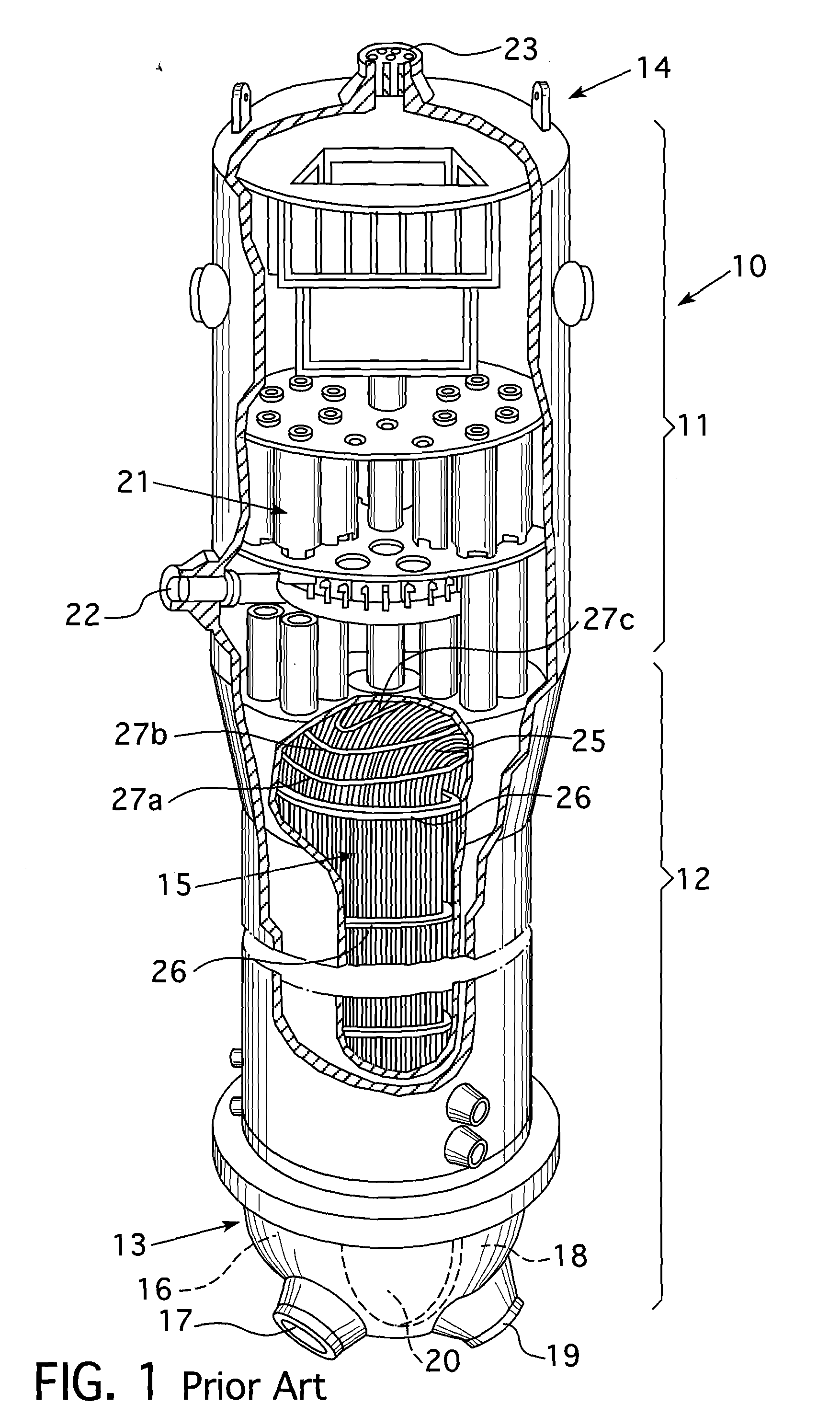
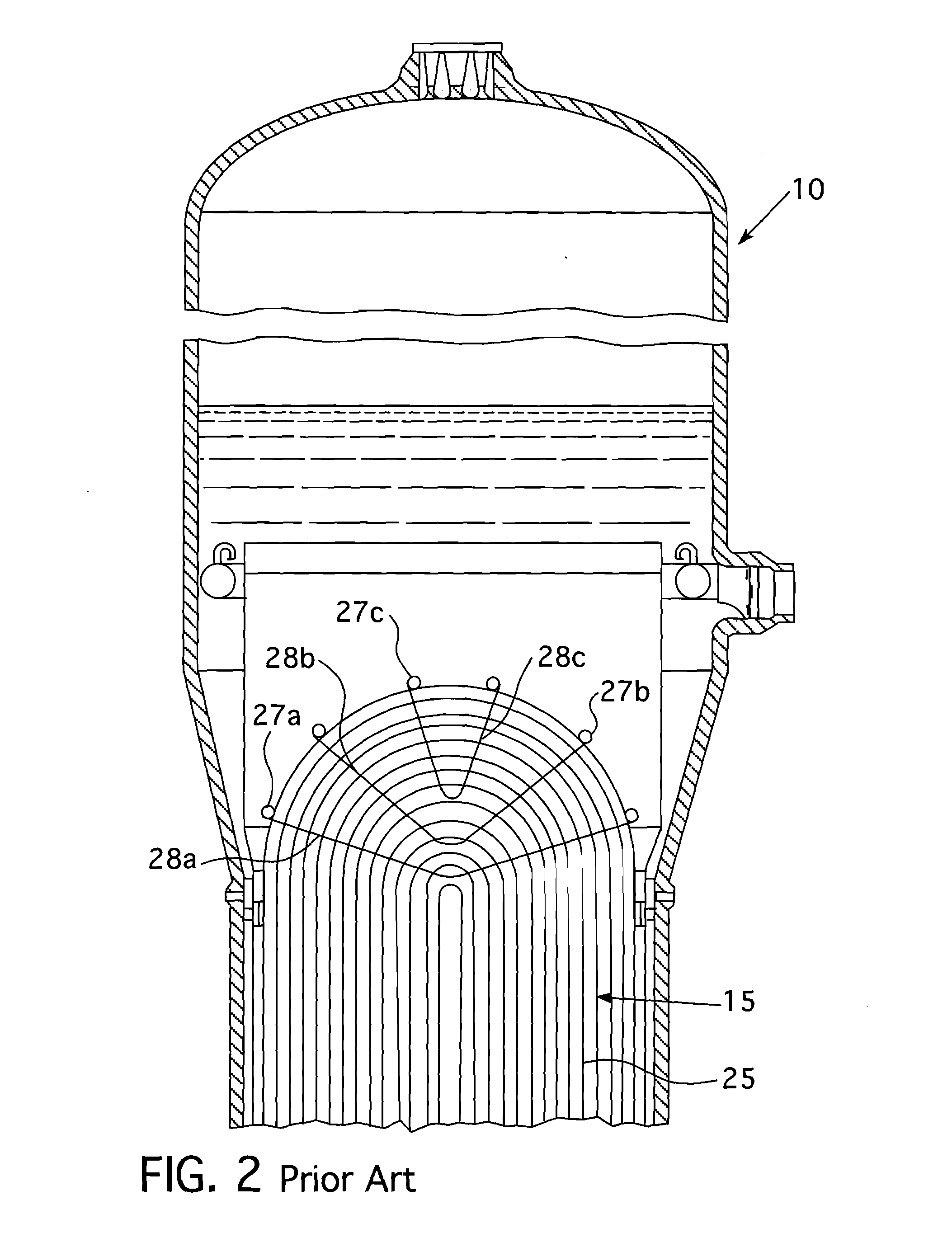
[0024]Referring now to the drawings where like features are referred to by the same reference numbers among the various figures and, in particular, to FIGS. 1 and 2 which depict a typical steam generator to which the present embodiment may be applied.

[0025]The nuclear steam generator 10 comprises a substantially cylindrical shell having an upper section 11 and lower section 12. A hemispherical head or channel head 13 is sealingly attached at the lower end of the lower portion 12. An upper head 14 is sealingly attached to the upper end of the upper portion 11. A bundle 15 of U-shaped tubes is disposed within the lower portion 12. One end of the tube bundle 15 is in flow communication with the hot leg 16 of the channel head 13 and a primary coolant flow inlet nozzle 17. The other open end of the tube bundle 15 is in flow communication with the cold leg 18 of the channel head 13 and a primary coolant flow outlet nozzle 19. A partition 20 divides the hot leg 16 and cold leg 18 of the ch...


PUM

PropertyMeasurementUnit
distanceaaaaaaaaaa
forceaaaaaaaaaa
displacementaaaaaaaaaa

Abstract

An automated tool and method for spacing a gap between the anti-vibration bars and the flow tubing in the bend region of a tube bundle of a U-tube steam generator, prior to welding, during manufacture. The tool comprises two toggle clamp elements attached to a scissors assembly, which are actuated by a linear drive motor in line with a force gauge, and coupled to a distance measuring device. The tool is operated by first attaching the toggle clamps respectively to two adjacent anti-vibration bars. A linear drive motor on the tool is then cycled and readouts of force and distance are plotted on a curve to determine the point of contact between the anti-vibration bar and the tube. The computer then automatically cycles the drive motor to adjust the gap to a desired range of position coordinates adjacent the point at which the curve markedly changes slope.

Description

BACKGROUND[0001]1. Field[0002]This invention relates in general to heat exchangers and to apparatus for preventing vibration within the tube bend region of a U-tube heat exchanger and more particularly to apparatus and methods for the spacing of anti-vibration bars in the tube lanes between tube columns in the U-bend region of such heat exchangers.[0003]2. Related Art[0004]U-shaped heat exchangers are commonly employed in pressurized water nuclear reactor steam generators. A nuclear steam generator generally comprises a vertically oriented shell, a plurality of U-shaped tubes disposed in the shell so as to form a tube bundle, a tube sheet for supporting the tubes at the ends opposite the U-like curvature, a dividing plate that cooperates with the tube sheet and a hemispheric channel head to form a primary fluid inlet header at one end of the tube bundle and a primary fluid outlet header'at the other end of the tube bundle. A primary fluid inlet nozzle is in fluid communication with ...

Claims


Application Information

Patent Timeline
Patent Type & Authority Applications(United States)
IPC IPC(8): B23P15/26B23P21/00B23P19/00
CPCF22B37/003F16L55/035F28F9/0132F28F2280/00F28D7/06F28D2021/0054Y10T29/53117Y10T29/53122Y10T29/49393Y10T29/49391Y10T29/53022Y10T29/53F28F2265/30B23P15/26B23P19/00B23P21/00
Inventor WEPFER, ROBERT M.
Owner WESTINGHOUSE ELECTRIC CORP
Why Eureka
Try Eureka