
Battery exchanging method for electric vehicle

a technology for electric vehicles and batteries, applied in the direction of electric generators, vehicle maintenance, manufacturing tools, etc., can solve the problems of removing any economic efficiency of charging facilities, constant price rise, and long charging time inconvenience for drivers

Active Publication Date: 2012-12-06
KOOKMIN UNIV IND ACAD COOP FOUND
View PDF0 Cites 136 Cited by
  • Summary
  • Abstract
  • Description
  • Claims
  • Application Information

AI Technical Summary

Benefits of technology

[0013]Embodiments of the inventive concept provide a battery exchange method by which a battery can be exchanged from an upper portion of an electric vehicle without inconvenience in the operation of the vehicle.
[0014]Another embodiment of the inventive concept provides the battery exchange method by which the battery can be exchanged efficiently and conveniently, by automatically performing a battery replacing task through communication between an electric vehicle and a battery charge station.

Problems solved by technology

However, fossil energy is a finite resource and is thus becoming depleted over time and the price is constantly rising.
In particular, fossil energy emits various exhaust gases that pollute the environment in the process of use and a large quantity of carbon dioxide that is a main contributing factor to global warming.
However, since electric vehicles use batteries charged in a plug-in manner, unlike a vehicle that uses oil (gasoline, diesel, etc.) or natural gas, the long charging time is inconvenient for drivers and removes any economic efficiency for companies operating charging facilities.
However, in the conventional battery replacing method, since the battery replacement is performed on the floor of the electric vehicle, the replacing system should be installed underground, and thus there are drawbacks in that it becomes very expensive to install and operate the replacing system.

Method used


Image

  • Battery exchanging method for electric vehicle
  • Battery exchanging method for electric vehicle
  • Battery exchanging method for electric vehicle

Examples


Embodiment Construction

[0029]Various embodiments will now be described more fully with reference to the accompanying drawings in which some embodiments are shown. These inventive concepts may, however, be embodied in different forms and should not be construed as limited to the embodiments set forth herein. Rather, these embodiments are provided so that this disclosure is thorough and complete and fully conveys the inventive concept to those skilled in the art. In the drawings, the sizes and relative sizes of layers and regions may be exaggerated for clarity.

[0030]Hereinafter, specific embodiments of the inventive concept will be described with reference to the drawings.

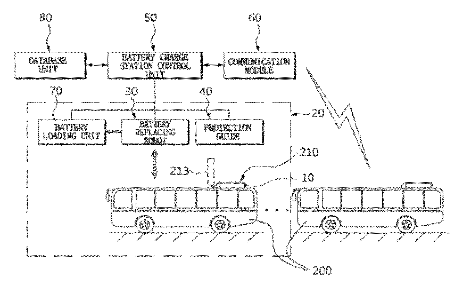
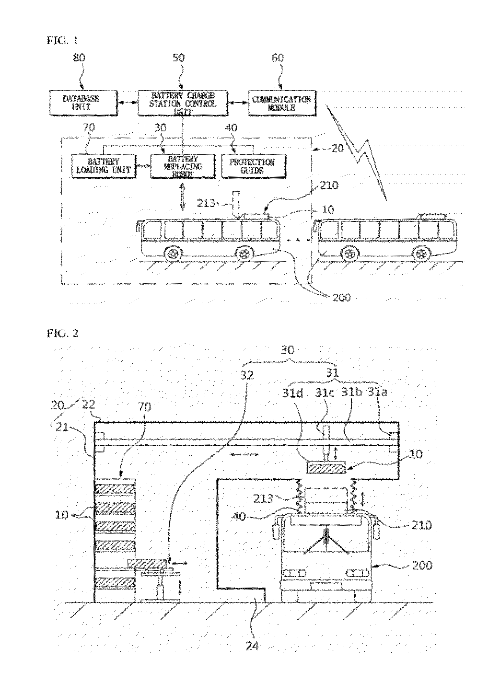
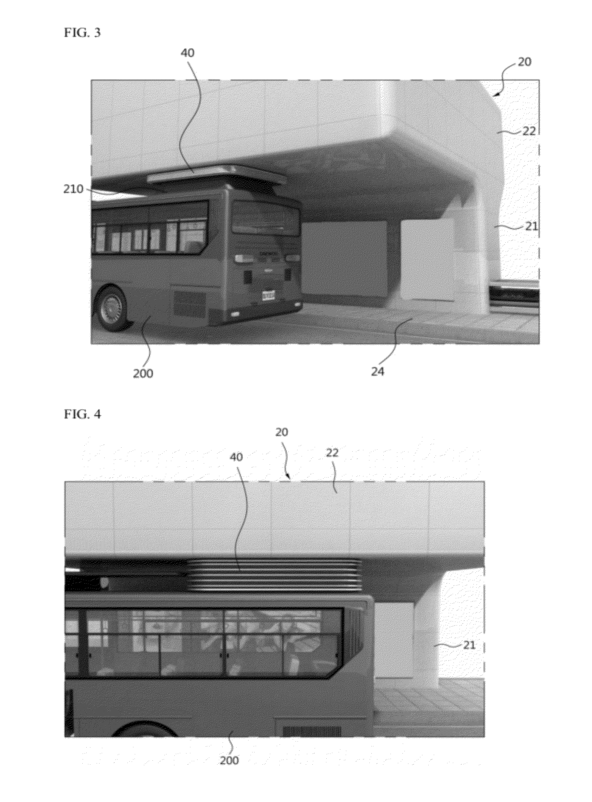
[0031]FIG. 1 is a block diagram for explaining a battery exchanging system for an electric vehicle in accordance with an embodiment of the inventive concept, FIG. 2 is a schematic configuration view for explaining a battery exchanging system for an electric vehicle in accordance with an embodiment of the inventive concept, and FIG. 3 is a ...


PUM

PropertyMeasurementUnit
movementaaaaaaaaaa
movementsaaaaaaaaaa
structureaaaaaaaaaa

Abstract

Provided is a battery exchange method for an electric vehicle. The battery exchange method includes (a) opening a protection cover of a battery mounting module installed at an upper portion of the electric vehicle, and transmitting an open signal to a battery charge station; (b) releasing a locking unit of a pre-mounted battery, and transmitting an unlocking signal to the battery charge station; (c) determining and storing a mounting location of the battery using an image sensor; (d) controlling movements and operations of a battery replacing robot when the unlocking signal is confirmed, and ejecting the pre-mounted battery from a battery seating base of the battery mounting module; (e) controlling movements and operations of the battery replacing robot to move a prepared fully charged battery into the battery mounting module, and mounting the fully charged battery on the battery seating base in the battery charge station.

Description

CROSS-REFERENCE TO RELATED APPLICATION[0001]This application claims priority under 35 U.S.C. §119 to Korean Patent Application No. 10-2011-0052913 filed on Jun. 1, 2011, the disclosure of which is hereby incorporated by reference in its entirety.BACKGROUND[0002]1. Field of the Invention[0003]Embodiments of the inventive concept relate to battery exchange for an electric vehicle and in particular, to technology by which a battery of an electric vehicle can be exchanged easily, conveniently and quickly.[0004]2. Description of Related Art[0005]A vehicle, which is essential to human life and socioeconomic activities, is a moving means that moves using fossil energy such as oil. However, fossil energy is a finite resource and is thus becoming depleted over time and the price is constantly rising.[0006]In particular, fossil energy emits various exhaust gases that pollute the environment in the process of use and a large quantity of carbon dioxide that is a main contributing factor to glob...

Claims


Application Information

Patent Timeline
Patent Type & Authority Applications(United States)
IPC IPC(8): H02J7/00H01M8/00
CPCB60S5/06Y10T29/53278Y10T29/53135Y02T90/124B60L53/80Y02T90/16Y02T10/70Y02T10/7072H02J7/00B60L50/50Y02T90/12
Inventor PARK, JUN SEOKKIM, WON-KYUPARK, HEE-JEINGMOON, HEE SEOKCHOI, WOONGCHULJEONG, JAYILYU, CHI MANJUNG, DO YANGSHIN, YONG-HARKPARK, JAE-HONG
Owner KOOKMIN UNIV IND ACAD COOP FOUND
Learn More