
Transmission power control method, communication device and program

a technology of transmission power control and communication device, applied in the direction of transmission monitoring, power management, wireless communication, etc., can solve the problems of limited actual opportunity of use, difficult to receive a radio signal (primary signal) locally in one primary usage node, etc., to achieve more communication opportunities and suppress interference

Active Publication Date: 2012-12-06
SONY GRP CORP
View PDF6 Cites 26 Cited by
  • Summary
  • Abstract
  • Description
  • Claims
  • Application Information

AI Technical Summary

Benefits of technology

This approach enhances communication opportunities for secondary usage while minimizing interference with primary systems, ensuring reliable communication quality by dynamically managing transmission power levels.

Problems solved by technology

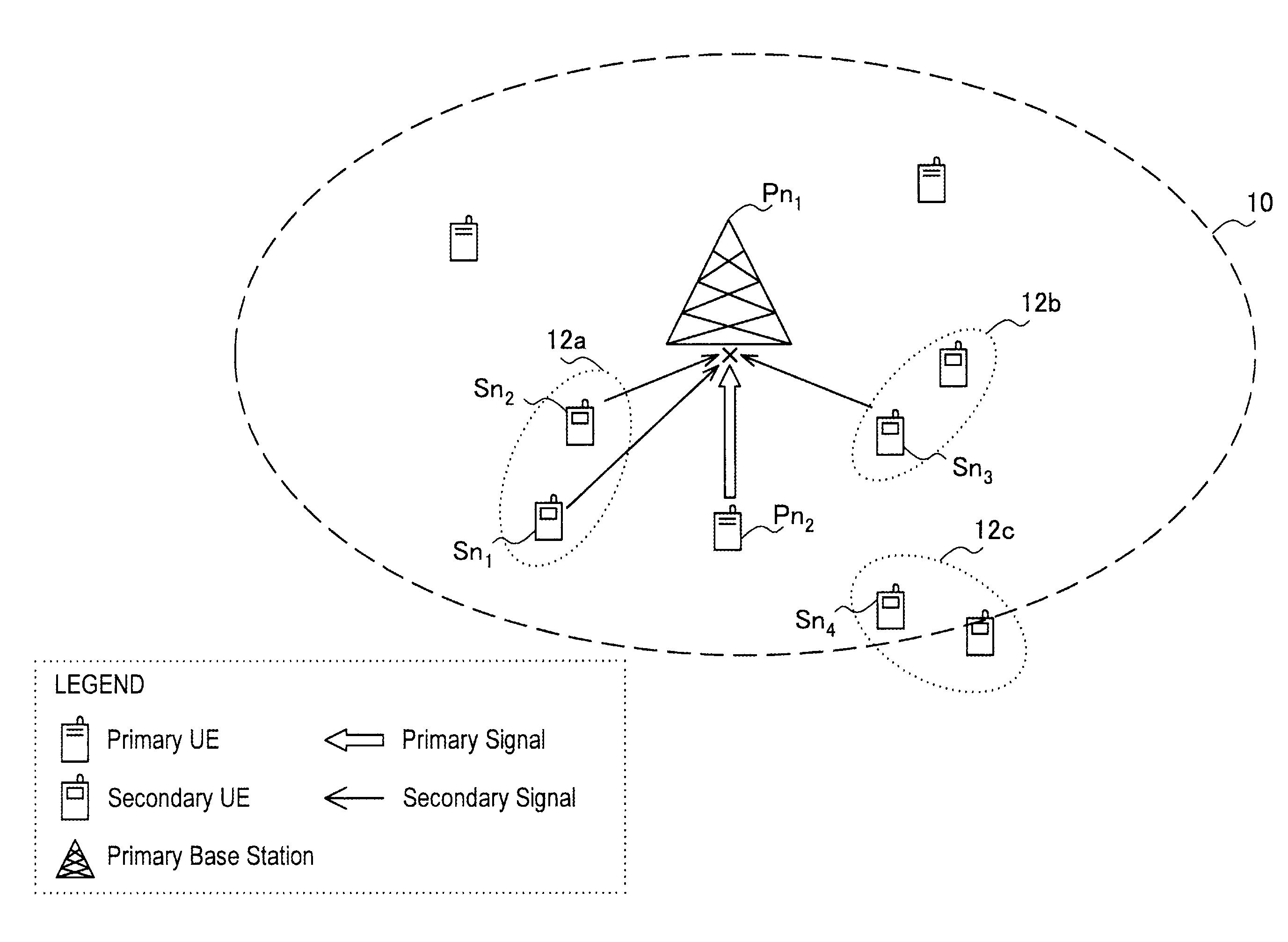
In order to make full effective use of a limited spectrum, it is not sufficient to achieve secondary usage of the above-described white space, which is a spectrum in an area where a communication service related to primary usage (which is referred to hereinafter as a first communication service) is not provided.
One reason is that secondary usage of the white space is utilization of a spectrum that is apparently available in the long and medium terms in a particular region, and an actual opportunity of usage is limited to an area where there are only a small number of users of the first communication service.
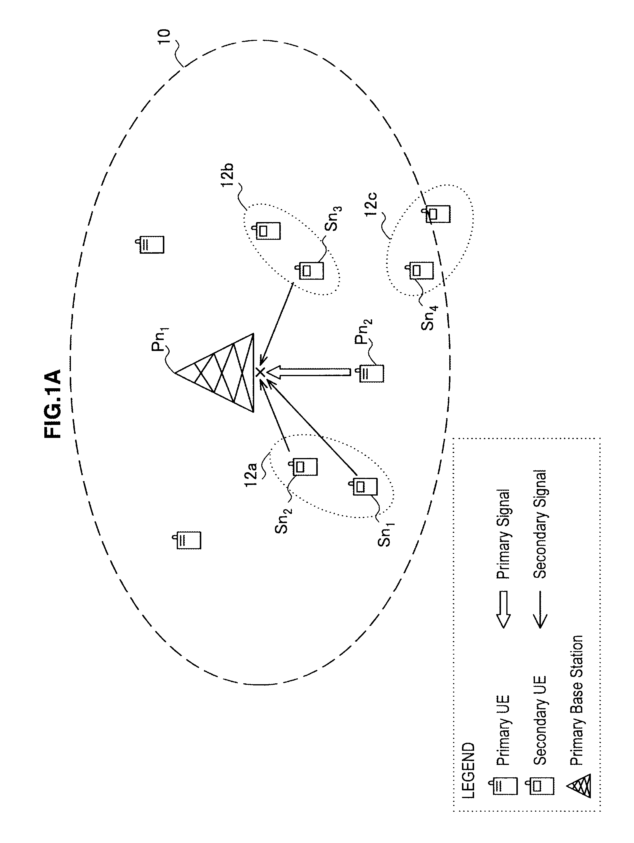
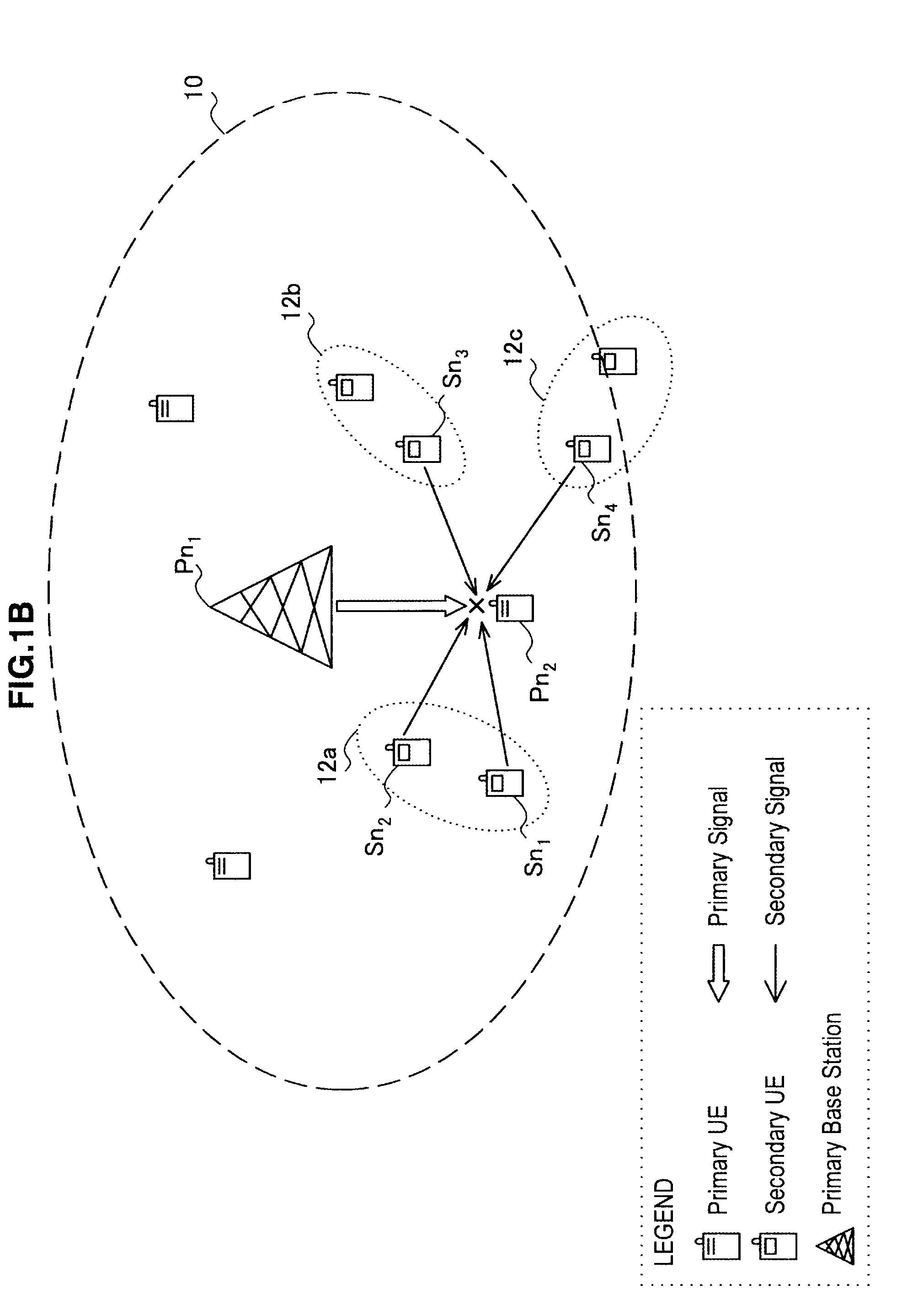
For example, because the technique taught by Inage et al. decreases the entire capacity of the primary system in one cell at a constant rate and allocates the amount of decrease to the secondary system, there remains a possibility it becomes difficult to receive a radio signal (primary signal) locally in one primary usage node due to interference of the secondary usage node in the nearby vicinity.

Method used


Image

  • Transmission power control method, communication device and program
  • Transmission power control method, communication device and program
  • Transmission power control method, communication device and program

Examples


first embodiment

2. First Embodiment

[2-1. Overview of Communication System]

[0122]FIG. 4 is an explanatory view to describe an overview of a communication system according to a first embodiment of the present invention.

[0123]FIG. 4 shows a primary system 102 that operates a first communication service and secondary systems 202a and 202b that respectively operate second communication services. The primary system 102 includes a management node 100 and a plurality of primary usage nodes 104.

[0124]The management node 100 is a primary usage node that has a role to manage secondary usage of the spectrum assigned to the first communication service. Although the management node 100 is a base station in the example of FIG. 4, the management node 100 is not limited thereto. Specifically, the management node 100 may be a primary usage node different from a base station, or it may be another node (e.g. a data server etc.) that is connected to a base station by wired or wireless means. In this embodiment, the man...

second embodiment

3. Second Embodiment

[0171]In the first embodiment of the present invention, transmission powers allocated to the second communication service is determined by the primary usage node (management node) which is accessible to the database that stores the location data of the primary usage node. This is a passive technique from the viewpoint of the terminal device (UE) that makes secondary usage. On the other hand, the terminal device that makes secondary usage may acquire necessary parameters and determine the acceptable transmission power for the second communication service in an active manner. In this section, a case where the terminal device that makes secondary usage actively determines the acceptable transmission power is described as a second embodiment of the present invention.

[3-1. Overview of Communication System]

[0172]FIG. 10 is an explanatory view to describe an overview of a communication system according to the second embodiment of the present invention.

[0173]FIG. 10 show...

third embodiment

4. Third Embodiment

[0195]In the first embodiment, the acceptable transmission power for secondary usage is determined by the management node in a passive way from the viewpoint of the terminal device that makes secondary usage of a spectrum. Further, in the second embodiment, the acceptable transmission power for secondary usage is determined by the terminal device acting as a coordinator of secondary usage in an active way from the viewpoint of the terminal device that makes secondary usage of a spectrum. By making secondary usage of a spectrum within the range of the acceptable transmission power determined by any or those techniques, interference occurring in the primary usage node is suppressed. Further, in order to optimize the opportunity of communication attained by secondary usage of a spectrum within the range of the limited transmission power, it is desirable that the transmission power is allocated adaptively to the secondary usage nodes that subscribe to the second commu...


PUM


Abstract

There is provided a method for controlling a transmission power in a second communication service making secondary usage of a spectrum assigned to a first communication service, with use of any node of one or more secondary usage node that transmits a radio signal of the second communication service, comprising the steps of: acquiring an acceptable interference power allocated to the second communication service; calculating a total sum of interference power levels on the first communication service based on transmission powers respectively required for the one or more secondary usage node; and excluding any secondary usage node of the one or more secondary usage node from allocation of the transmission power when the calculated total sum of interference power levels is larger than the acceptable interference power.

Description

RELATED APPLICATIONS[0001]This application claims the benefit under 35 U.S.C. §120 and is a continuation (CON) of U.S. application Ser. No. 12 / 840,831, entitled “TRANSMISSION POWER CONTROL METHOD, COMMUNICATION DEVICE AND PROGRAM” filed on Jul. 21, 2010, which is herein incorporated by reference in its entirety. Foreign priority benefits are claimed under 35 U.S.C. §119(a)-(d) or 35 U.S.C. §365(b) of Japanese application number 2009-179368, filed Jul. 31, 2009 and Japanese application number 2010-110013, filed May 12, 2010.BACKGROUND OF THE INVENTION[0002]1. Field of the Invention[0003]The present invention relates to a transmission power control method, a communication device and a program.[0004]2. Description of the Related Art[0005]Discussions have been taking place recently regarding secondary usage of a spectrum assigned for primary usage to provide a secondary communication service depending on the use condition of the spectrum. For example, the standard specification for allo...

Claims


Application Information

Patent Timeline
Patent Type & Authority Applications(United States)
IPC IPC(8): H04W52/24H04W24/02H04B15/00
CPCH04W52/143H04W52/16H04W52/46H04W52/242H04W52/243H04W52/24H04W16/14H04W52/34H04W64/00
Inventor SAWAI, RYO
Owner SONY GRP CORP
Learn More