Lock structure

a technology of lock structure and lock body, which is applied in the field of lock structure, can solve the problems of high possibility of electronic devices being stolen, awkward or inconvenient operation of the lock structure,

Active Publication Date: 2012-12-13
SINOX CO LTD
View PDF2 Cites 10 Cited by
  • Summary
  • Abstract
  • Description
  • Claims
  • Application Information

AI Technical Summary

Benefits of technology

[0007]It is an object of the present invention to provide a lock structure for preventing valuable products, such as electronic devices, from being stolen through an improved rotatable fastener of the lock structure.

Problems solved by technology

Unfortunately, because of the popularity of and demand for such devices, the relatively high cost, the relatively small and / or portable size, and the adaptability of such devices to most anyone's needs, the possibility of these electronic devices being stolen is high.
However, operation of these lock structures can be awkward or inconvenient.

Method used


Image

  • Lock structure
  • Lock structure
  • Lock structure

Examples


Embodiment Construction

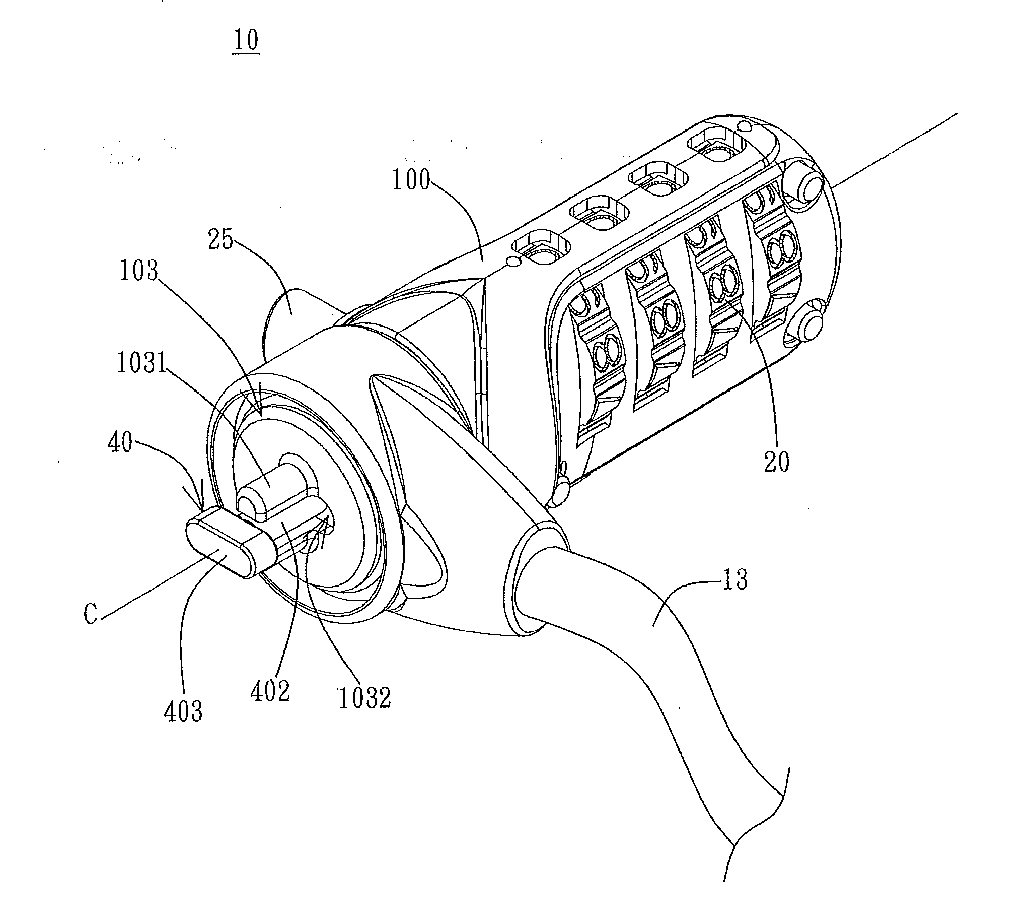
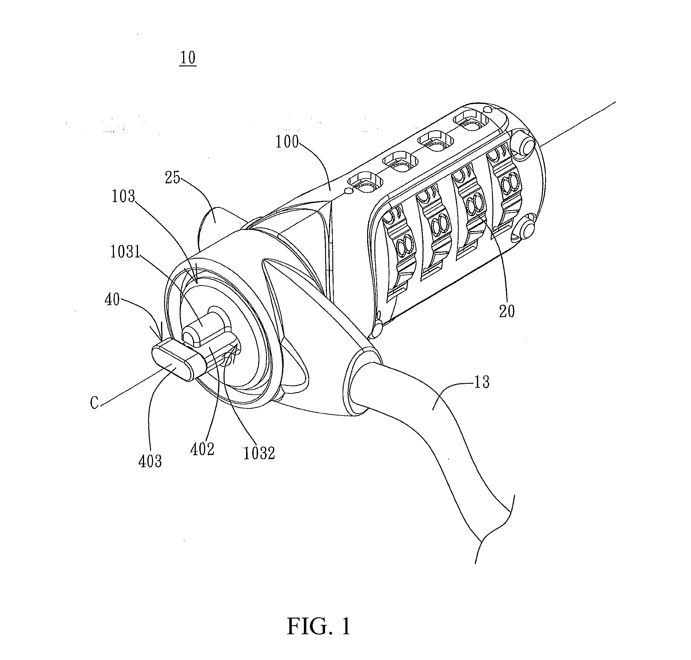
[0041]The present invention provides a lock structure for electronic devices. Electronic devices include, but are not limited to, portable devices such as laptop or notebook computers. As FIG. 1 shows, a lock structure 10 includes a housing 100, a lock body 20, an operation device 25, and a rotatable fastener 40. The housing 100 encloses at least one chamber or interior for at least partially accommodating the lock body 20, the operation device 25, and the rotatable fastener 40. A flexible cable 13 can be connected to the housing 100 for securing the lock structure and the interconnected electronic device to a stationary object, such as a table, or a fixed or immovable object. A protruding portion 1031 is disposed on an end of the housing 100. The protruding portion 1031 includes two columnar structures spaced apart from each other. The two columnar structures can be, for example, two columns or posts having a semi-circular cross-section configured to restrict one-dimensional latera...


PUM


Abstract

A lock structure for an electrical device is provided. The lock structure includes a rotatable fastener, a lock body, an operation device, and a housing. The lock body is disposed at least partially in the housing, connected with the operation device, and couples with a driving portion. When the lock body is in an unlocked state, the lock body allows the driving portion to move the rotatable fastener. Simultaneously, the operation device can move the driving portion to change the orientation of the rotatable fastener, resulting in the connection/detachment of the lock structure and the electronic device. When the lock body is in a locked state, movement of the driving portion is restricted and the operation device cannot directly or indirectly rotate the rotatable fastener, resulting in the secure connection of the lock structure and the electronic device.

Description

CROSS REFERENCE TO RELATED APPLICATIONS[0001]The present application is a continuation-in-part of U.S. application Ser. No. 13 / 115,816 entitled “Lock Structure” filed May 25, 2011, and claims the benefit of U.S. Provisional Application Ser. Nos. 61 / 361,775 filed Jul. 6, 2010, and 61 / 420,658 filed Dec. 7, 2010, the entirety of each is incorporated herein by this reference.BACKGROUND OF THE INVENTION[0002]1. Field of the Invention[0003]The present invention generally relates to lock structures, particularly, to a burglar proof lock for electronic devices.[0004]2. Description of the Prior Art[0005]Consumer electronic products have played an important role in modern life. Moreover, because of fast modern lifestyle and the demand for instant information, portable electronic devices have become essential in the lives of most people. Unfortunately, because of the popularity of and demand for such devices, the relatively high cost, the relatively small and / or portable size, and the adaptabi...

Claims


Application Information

Patent Timeline
Patent Type & Authority Applications(United States)
IPC IPC(8): E05B73/00
CPCE05B37/025E05B73/0082E05B73/0005Y10T70/796Y10T70/40Y10T70/5009Y10T70/7706Y10T70/7718Y10T70/7983
Inventor YU, CHANG-CHIANGWU, CHUN-SHENG
Owner SINOX CO LTD
Why Eureka
Try Eureka