Steam Generation Boiler

Active Publication Date: 2012-12-13
FOSTER WHEELER ENERGIA OY
View PDF10 Cites 2 Cited by
  • Summary
  • Abstract
  • Description
  • Claims
  • Application Information

AI Technical Summary

Benefits of technology

[0011]One object of the invention is, thus, to provide a steam generation boiler, the structure of the lower portion of which makes it possible to provide a high-power and large-size boiler better than before.
[0012]A special object of the invention is to provide a circulating fluidized bed once-through steam generation boiler, the structure of the lower portion of which makes it possible to provide a high-power and large-size boiler better than before.
[0014]By this kind of a solution, a steam generation boiler is provided, the structure of the end wall of which comprises steam pipes tapers towards the bottom portion, which structure is advantageous from the viewpoint of steam production. In particular, by this kind of a solution, a once-through steam generation boiler is provided, the structure of the end wall of which comprises steam pipes tapers towards the bottom portion, thus, enabling a sufficiently uniform heat exchange to each steam pipe in the structure, which structure is advantageous from the viewpoint of the operation of the once-through steam generation boiler.

Problems solved by technology

When the aim is to manufacture a high-power boiler, e.g., a boiler with a thermal capacity of several hundred megawatts, a large reaction volume and a significant amount of evaporation and superheating surface are required.
To arrange steam generator pipes on the wall plane in a tapering wall section is likely to become a problem, however, if the tapering is large enough.
This means, in practice, that it is disadvantageous for the operation of a once-through steam generation boiler if the heat delivery surfaces in the various portions of the furnace are exposed to a different impact of the fluidized bed and heat exchange, respectively, depending, e.g., on the structures of the lower portion of the grid and the furnace and on the process control.
This kind of changing of the pipe size and fin width in the wall region, however, requires a plurality of welding operations, which increases the number of working phases and the risk of leakage.

Method used


Image

  • Steam Generation Boiler
  • Steam Generation Boiler
  • Steam Generation Boiler

Examples


Embodiment Construction

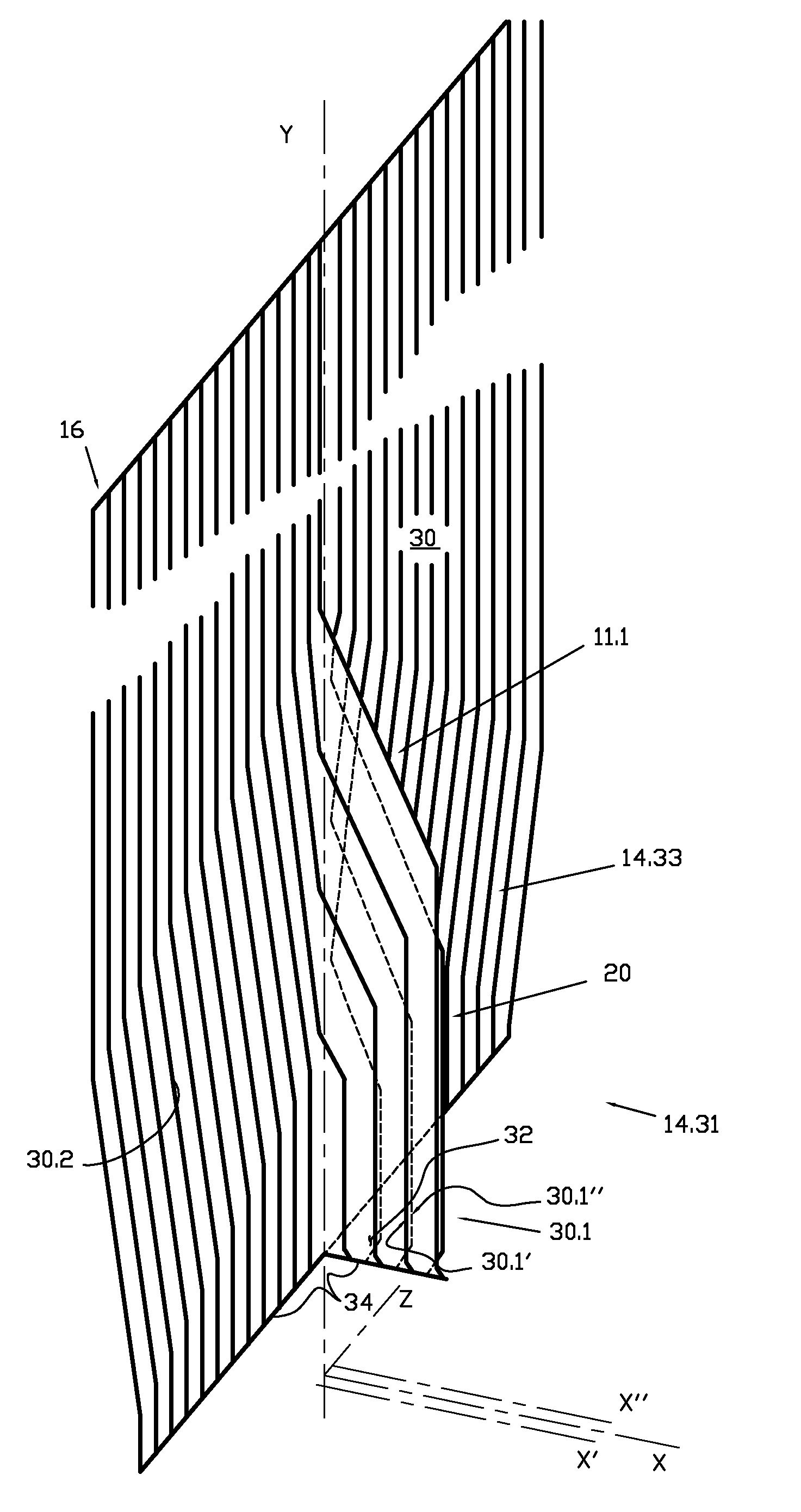
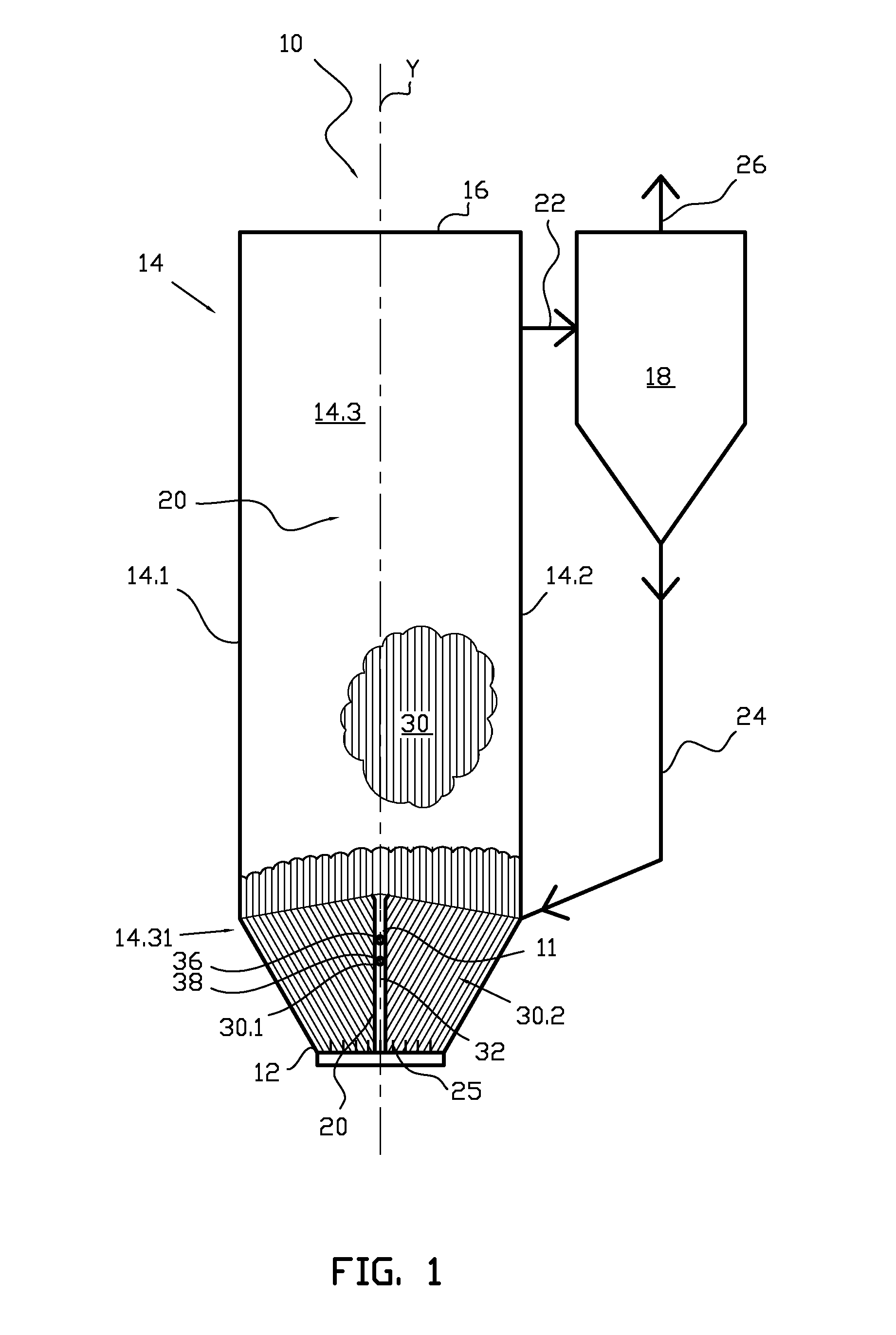
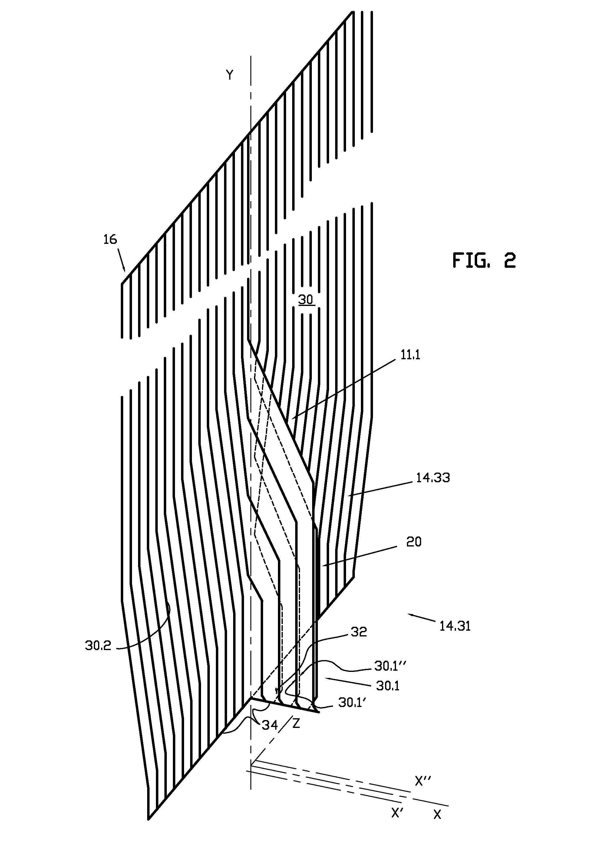
[0029]FIG. 1 schematically shows one embodiment of the steam generation boiler 10 according to the invention, the type of which boiler 10 is a circulating fluidized bed once-through steam generation boiler. The steam generation boiler 10 comprises a bottom portion 12 and a roof portion 16, and walls 14 extending between them. Further, it is obvious that a circulating fluidized bed once-through steam generation boiler comprises a number of such parts and elements that are not shown herein for the sake of clarity. The bottom portion 12, the roof portion 16, and the walls 14 form a reaction chamber 20, which, in the case of a boiler, is a furnace. The bottom portion 12 also includes a grid 25, through which, e.g., fluidization gas is led into the reactor. In addition, the fluidized bed reactor comprises a solids separator 18, which is, typically, a cyclone separator. The solids separator 18 is connected to the upper portion of the reaction chamber, in the vicinity of the roof section, ...


PUM


Abstract

A steam generation boiler includes a bottom portion and a roof portion, as well as walls that extend vertically between the bottom portion and the roof portion, thus forming a reaction chamber of the steam generation boiler, the walls of which reaction chamber embody a structure that includes steam generator pipes. The steam generation boiler includes, in its lower portion, at least one wall section tapering towards the bottom portion. A first group of steam pipes in the tapering wall section is arranged to pass from the wall plane into the reaction chamber and to extend from the wall plane to the bottom portion of the steam generation boiler on the side of the reaction chamber forming a wall in the reaction chamber, and a second group of steam pipes is arranged to pass to the bottom portion along the wall plane.

Description

CROSS REFERENCE TO RELATED APPLICATIONS[0001]This application is a U.S. national stage application of PCT International Application No. PCT / FI2011 / 050012, filed Jan. 12, 2011, published as International Publication No. WO 2011 / 086233 A1, and which claims priority from Finnish patent application number 20105027, filed Jan. 15, 2010.FIELD OF THE INVENTION[0002]The invention relates to a steam generation boiler.BACKGROUND OF THE INVENTION[0003]The reaction chamber of a circulating fluidized bed once-through steam generation boiler typically comprises an inner portion that has a rectangular horizontal cross section and is defined by four sidewalls, a bottom and a roof, in which inner portion, bed material containing solids and, e.g., fuel, is fluidized by means of fluidization gas, normally, by means of oxygenous primary gas required by the exothermic reactions taking place in the reaction chamber, to be led through the bottom of the reaction chamber. The inner portion, i.e., the reacto...

Claims


Application Information

Patent Timeline
IPC IPC(8): F22B31/00F23C10/18F22B29/06F22B37/10
CPCF22B29/062F23M5/08F23C10/18F22B31/0038F22B21/341F22B31/0092F22B37/10F22B37/38F22B21/00F22B31/00
Inventor LANKINEN, PENTTI
Owner FOSTER WHEELER ENERGIA OY
Why Eureka
Try Eureka