Visual Change Cue For Communicating Manufacturing Issues Of A Custom Part

a technology of manufacturing problems and visual cues, applied in the field of design and fabrication of custom parts, can solve the problems of complex communication between the moldmaker and the customer, complex decision-making, and problems that remain, and achieve the difficulty of customers in quickly understanding wher

Active Publication Date: 2012-12-13
PROTOLABS INC
View PDF10 Cites 40 Cited by
  • Summary
  • Abstract
  • Description
  • Claims
  • Application Information

AI Technical Summary

Benefits of technology

[0006]The present invention is a software method and system for communicating manufacturability issues. The customer's CAD file for the part is received and assessed for compliance with constraints of the manufacturing method for making the part. Preferably as an integral portion of the quotation returned to the customer, a computer rendering of the part is provided which graphically identifies the manufacturability issues. Sections without a particular manufacturability issue are shown translucently relative to at least one section identified as having that manufacturability issue such that the section having that manufacturability issue can be viewed through a more-forward face of the part. The section(s) identified as having that manufacturability issue is (are) depicted with a visual change cue, such as a throbbing effect, which enables the customer to immediately identify the locations on the part having the issue.

Problems solved by technology

Historically, moldmaking involves at least one face-to-face meeting between the moldmaker and the customer, with complex communication between the moldmaker and the customer and complex decisions made by the moldmaker regarding the construct of the mold.
While this automation has greatly improved the process of identifying manufacturability issues, communicating those issues to the customer and quoting manufacture of the mold and / or part, problems still remain.
One particular remaining problem is a difficulty of customers in quickly understanding where on a part a particular problem or needed change is located.
While the programmed flight pattern may proceed too quickly for some customers, other more experienced customers may consider the programmed flight pattern tedious in proceeding through viewing all the issues on a particular part.
The need for communication clarity increases as the variety of parts manufactured through automated methods becomes more and more complex.

Method used


Image

  • Visual Change Cue For Communicating Manufacturing Issues Of A Custom Part
  • Visual Change Cue For Communicating Manufacturing Issues Of A Custom Part
  • Visual Change Cue For Communicating Manufacturing Issues Of A Custom Part

Examples


Embodiment Construction

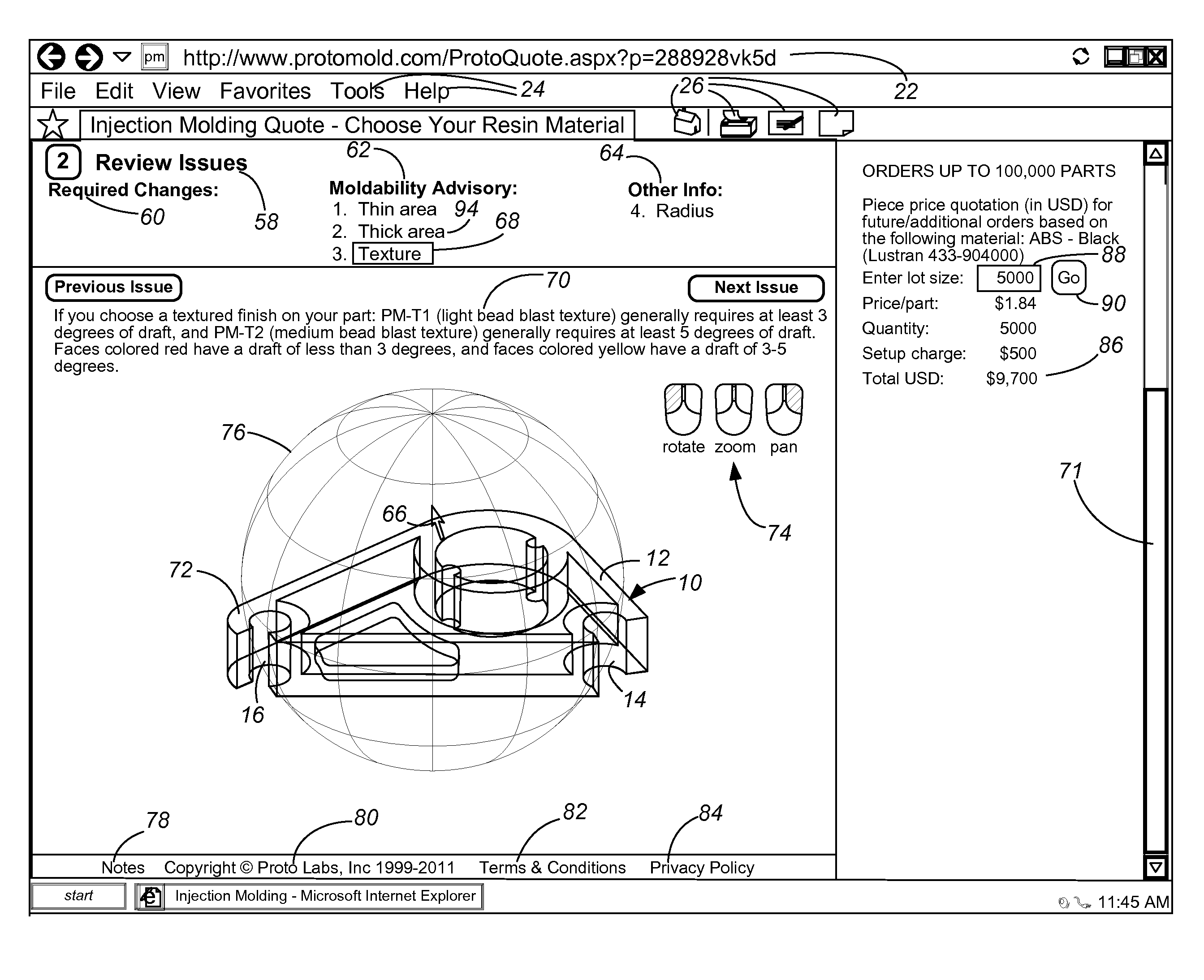
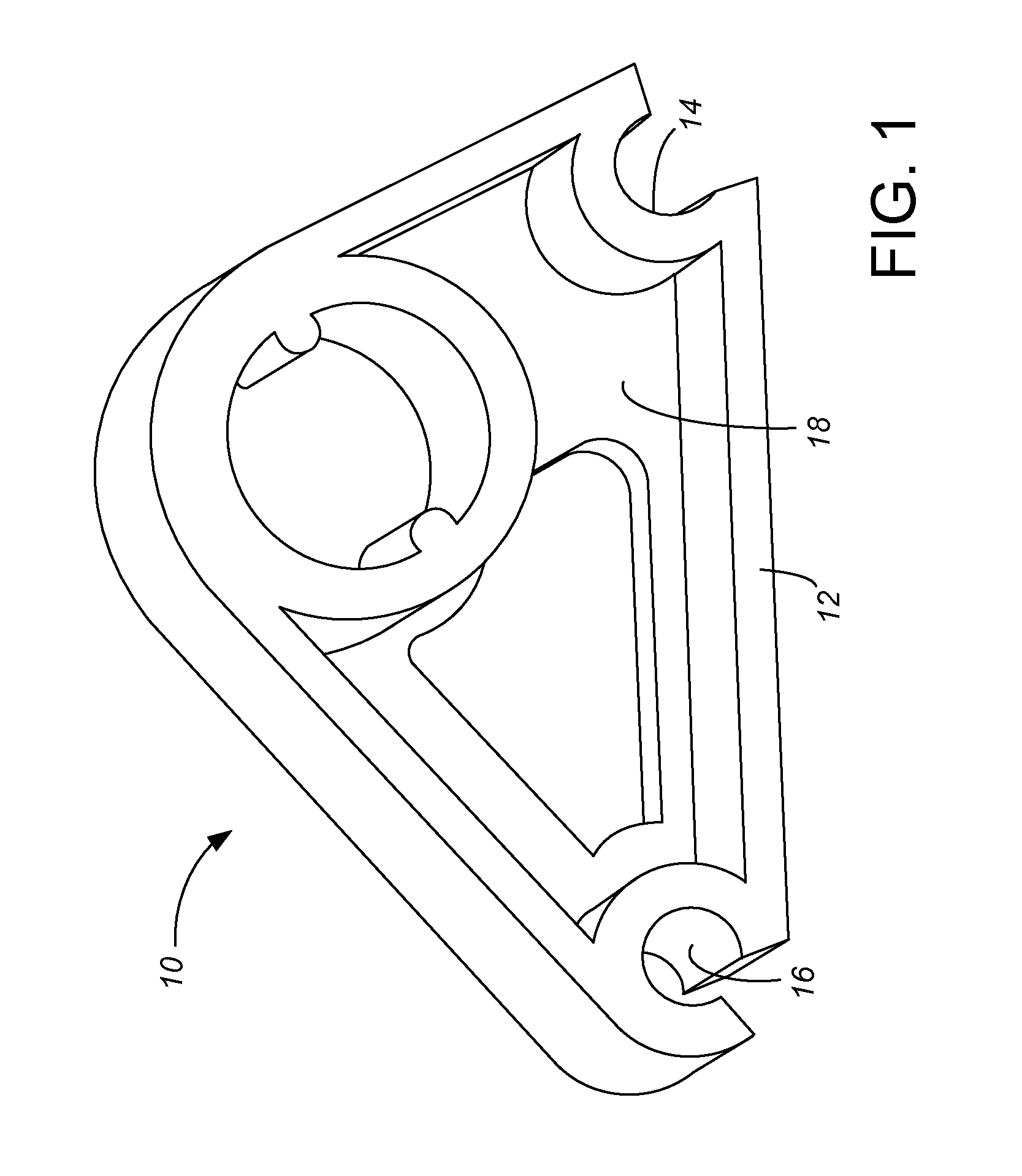
[0011]FIG. 1 shows an exemplary part 10 for discussion purposes of the inventive way to communicate issues associated with the manufacture of that part 10. In this example, the part 10 is a “cam” part custom designed by a customer named John One. In part because the cam 10 is custom-designed (i.e., not a staple article of commerce) by or for this particular customer, the cam 10 includes numerous features, none of which have commonly accepted names. For purposes of discussion, we will give names to several of these features, including a part outline flange 12, a 60° corner hole 14, a 30° corner hole 16 and a partial web 18. However, workers skilled in the art will appreciate that the customer may in fact have no name or may have a very different name for any of these features. Without commonly accepted names for these features, verbal communication about changes to one or more features of the cam part 10 is difficult. The present invention is particularly contemplated as a better way...


PUM


Abstract

Any issues associated with manufacture of a part are identified and highlighted on a part rendering. A software method and system then uses a visual change cue on the part rendering for communicating the manufacturability issues to the customer. The preferred visual change cue is a throbbing of the highlighting of the manufacturability issue, with the throbbing occurring in both color intensity and size. The part rendering depicts the part translucently, so throbbing manufacturability issues can be readily identified even if obscured behind a more-forward face of the part.

Description

CROSS-REFERENCE TO RELATED APPLICATION(S)[0001]None.BACKGROUND OF THE INVENTION[0002]The present invention relates to software supported methods, systems and tools used in the design and fabrication of custom parts, and in presenting information to customers for the customer to make selections or changes to help minimize the cost of manufacturing the customer's part.[0003]Injection molding, among other types of molding techniques, is commonly utilized to produce plastic parts from molds. Companies and individuals engaged in fabricating molds are commonly referred to as “moldmakers.” The moldmaking art has a long history of fairly gradual innovation and advancement. Molds are designed pursuant to a specification of the part geometry provided by a customer; in many cases, functional aspects of the plastic part also need to be taken into account. Historically, moldmaking involves at least one face-to-face meeting between the moldmaker and the customer, with complex communication betwee...

Claims


Application Information

Patent Timeline
Patent Type & Authority Applications(United States)
IPC IPC(8): G06F19/00G06F17/50
CPCG06F2217/12G06F17/50G06F30/00G06F2119/18Y02P90/02
Inventor HARTLOFF, MATTHEW
Owner PROTOLABS INC
Why Eureka
Try Eureka