Windshield wiper device

a technology of wiper device and windshield wiper, which is applied in the direction of vehicle maintenance, vehicle cleaning, domestic applications, etc., can solve the problems of severe injuries and the risk of the person striking, and achieve the effect of cost-effective, and minimizing the risk of injury to the person

Inactive Publication Date: 2012-12-20
ROBERT BOSCH GMBH
View PDF3 Cites 7 Cited by
  • Summary
  • Abstract
  • Description
  • Claims
  • Application Information

AI Technical Summary

Benefits of technology

[0002]It is the object of the invention to indicate a windshield wiper device for a motor vehicle, which minimizes a risk of injury by means of the windshield wiper device to a person impacting against the motor vehicle.
[0005]In the event of an impact of a person against the windshield wiper device, the first section can advantageously only exert small axial forces on the person, thus minimizing a risk of injury by means of the windshield wiper device to the person. Furthermore advantageously, the wiper shaft bearing can be dimensioned in such a manner that, prior to the impact, the wiper shaft is in an optimized position for the articulation of wiper blades and, during or after the impact, adopts a position which minimizes the risk of injury to a person.
[0006]A transition section with a predetermined breaking point for severing the frictional connection between the two axial sections in the event of overloading can be provided in a region between the first and the second axial section of the wiper shaft bearing. The effect which can advantageously be achieved by the predetermined breaking point is that, after an impact-induced overcoming of the breaking force which is required for releasing the predetermined breaking point, a telescopic movement of the first axial section into the second axial section requires only comparatively small forces. At the same time, if the predetermined breaking point is intact prior to the impact, forces can be simply, precisely and cost-effectively transmitted in the wiping mode of the windshield wiper device.
[0008]The first axial section can have a circular-cylindrical shape and the second axial section can have a hollow-cylindrical shape. As a result, during the telescopic displacement of the first axial section into the second axial section, a risk of the two axial sections becoming wedged can be minimized. Furthermore, the predetermined breaking point can be formed in a circular manner such that an axially symmetrical distribution of the breaking force of the predetermined breaking point can be obtained. The risk of injury to the impacting person can therefore be minimized irrespective of an impact direction of the person.
[0009]An outside diameter of the first axial section may be larger than an inside diameter of the second axial section. As a result, after being pushed into the second axial section, the first axial section may also adopt a tilted position, and therefore the first axial section and the parts connected thereto can be displaced in the tilting direction by the impacting person, thus enabling the risk of injury to the person to be lowered further.
[0010]The second axial section may have a fastening element for the fastening of the wiper shaft bearing. In particular, the fastening element may comprise a plug-in element for connection to a tubular plate of the windshield wiper device. An integrated wiper shaft bearing for a windshield wiper device can therefore be produced in a simple and cost-effective manner, wherein the wiper shaft bearing can differ only little, if at all, from a known wiper shaft bearing. In particular, the wiper shaft bearing can be designed to be produced as an injection molded component suitable for mass manufacturing.

Problems solved by technology

In the event of the motor vehicle colliding with a person outside the motor vehicle, there is the risk of the person striking, for example with the head, axially on the wiper shaft and on the bearing and suffering severe injuries.

Method used


Image

  • Windshield wiper device
  • Windshield wiper device
  • Windshield wiper device

Examples


Embodiment Construction

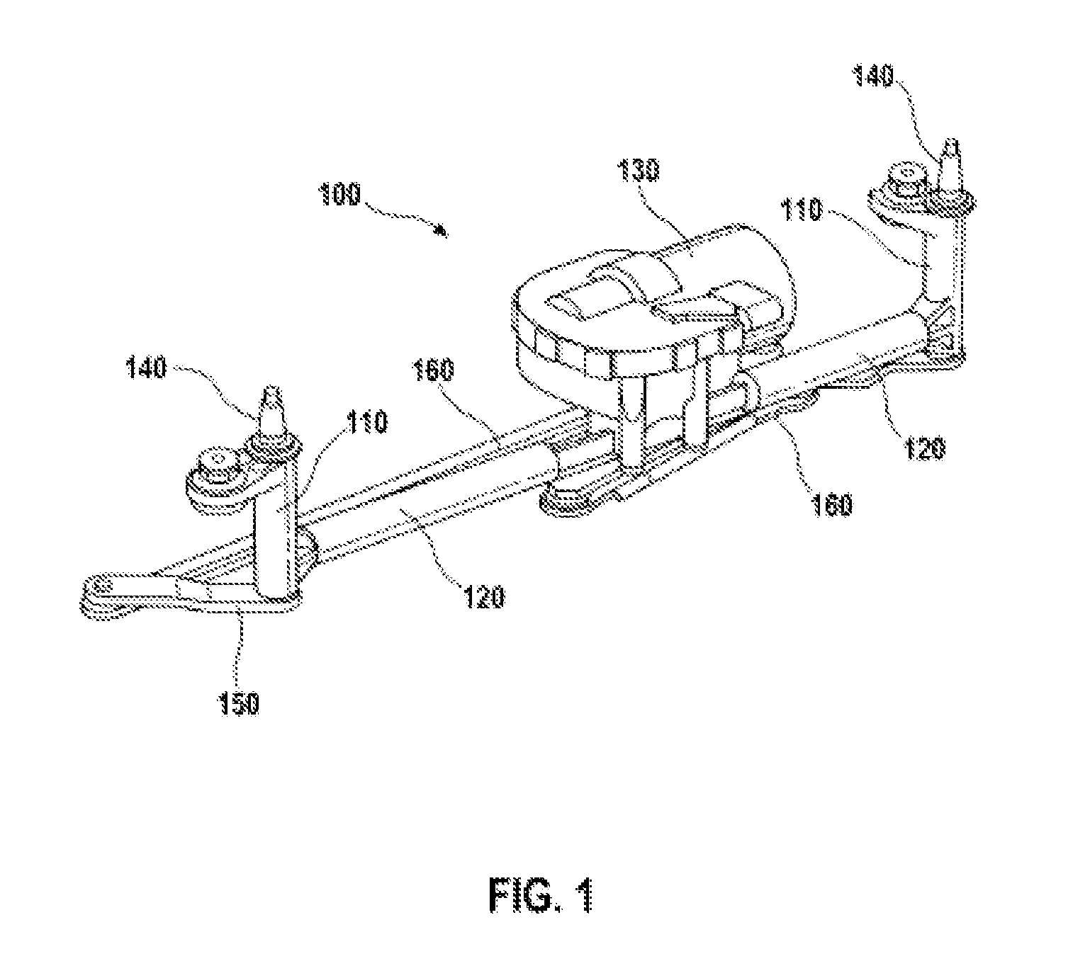
[0016]FIG. 1 shows a windshield wiper device 100 for use in a motor vehicle. The windshield wiper device 100 comprises two wiper shaft bearings 110, which are also called shaped tubes, and two tubular plates 120, by means of which the wiper shaft bearings 110 are fixed to a drive 130 of the windshield wiper device 100. A wiper shaft 140 runs through each of the wiper shaft bearings 110, the upper end of which wiper shaft is designed for the fastening of a wiper arm to a wiper blade (not shown). A wiper crank 150, which can be driven by the drive 130 by means of a connecting rod 160, is fastened in a torque-locking manner to the lower end of each wiper shaft 140. In an alternative embodiment, the wiper crank 150 can also be arranged at the upper end of the wiper shaft 140. In a further embodiment, the windshield wiper device 100 comprises fewer or more wiper shaft bearings 140, for example one or three.

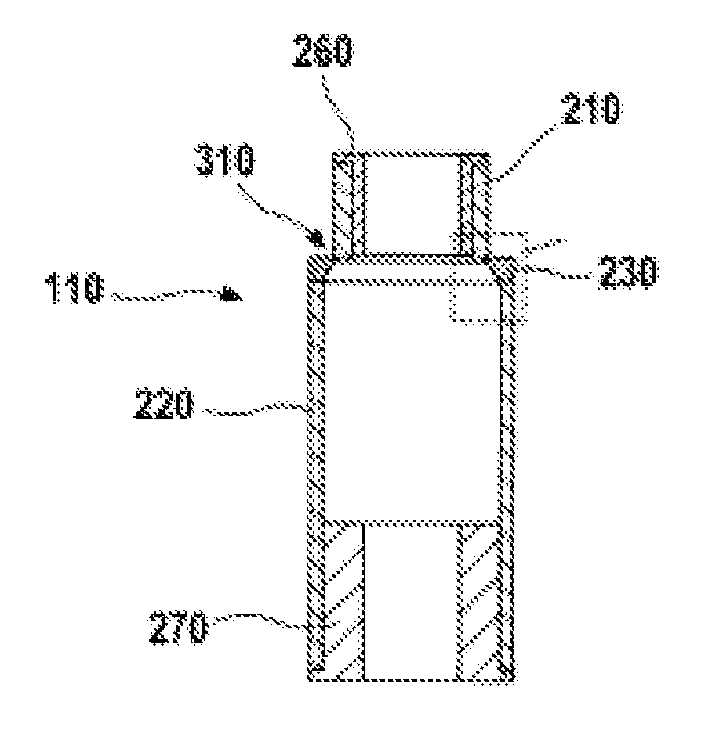
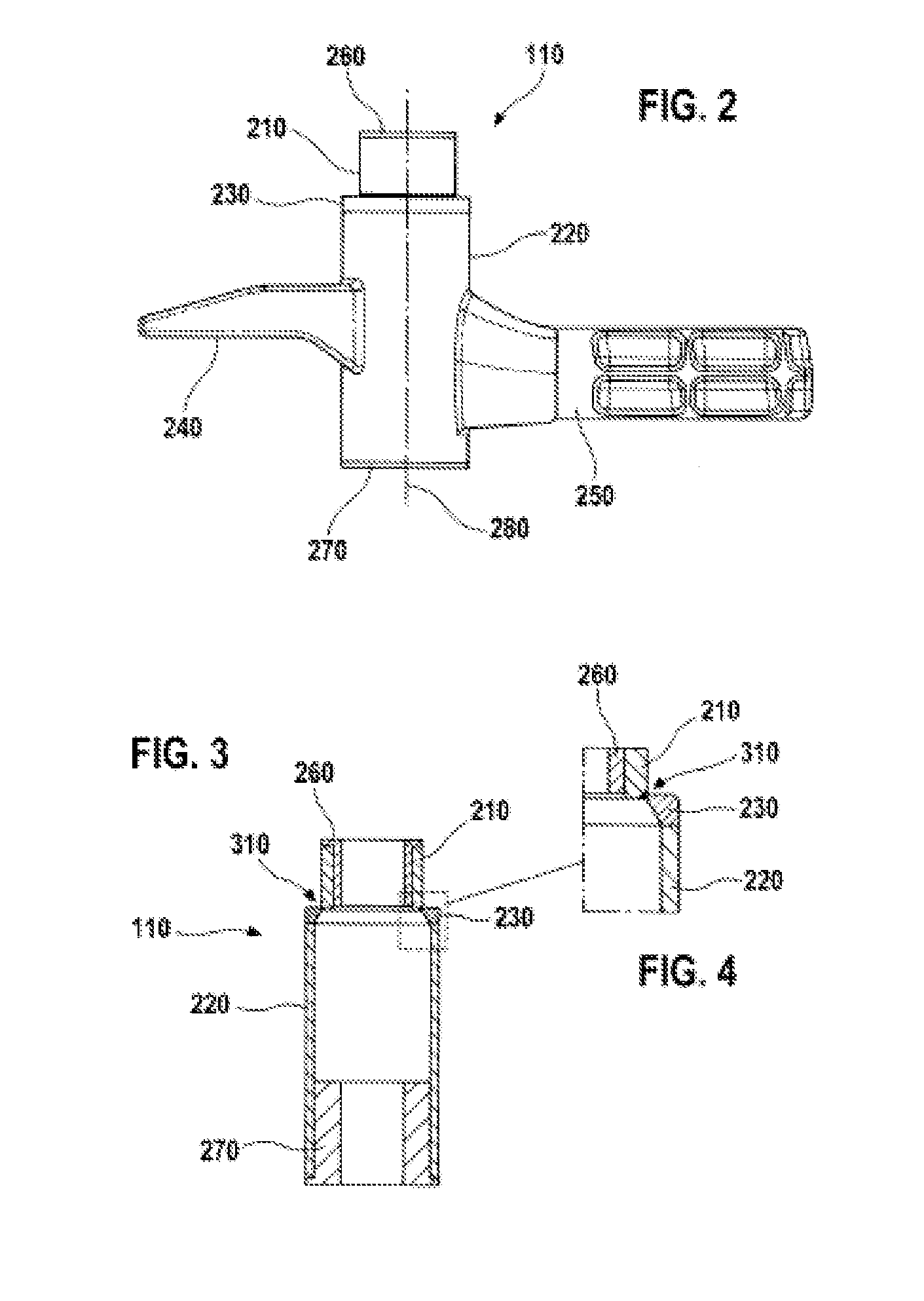
[0017]FIG. 2 shows the wiper shaft bearing 110 of the windshield wiper device 100 ...


PUM


Abstract

The invention relates to a windshield wiper device (100) comprising a wiper shaft bearing (110) for mounting a wiper shaft (140), wherein the wiper shaft bearing (110) has a first axial section (210) and a second axial section (220) connected to the first in a force-fit manner, and the first axial section (210) is designed to be telescopically inserted into the second axial section (220).

Description

BACKGROUND OF THE INVENTION[0001]Customary windshield wiper devices, as used in motor vehicles, comprise wiper arms which are moved in oscillating manner in a circular segment about a wiper shaft. The wiper shaft and a tubular bearing for receiving the wiper shaft extend in a direction running substantially perpendicularly to a surface of a window of the motor vehicle. In the event of the motor vehicle colliding with a person outside the motor vehicle, there is the risk of the person striking, for example with the head, axially on the wiper shaft and on the bearing and suffering severe injuries.SUMMARY OF THE INVENTION[0002]It is the object of the invention to indicate a windshield wiper device for a motor vehicle, which minimizes a risk of injury by means of the windshield wiper device to a person impacting against the motor vehicle.[0003]EP 1 939 055 A2 shows a windshield wiper device with a drive and two wiper shaft bearings which are fixed to the drive by means of tubular plates...

Claims


Application Information

Patent Timeline
Patent Type & Authority Applications(United States)
IPC IPC(8): B60S1/04
CPCB60S1/0425B60S1/3493B60S1/0488B60S1/0433B60S1/04B60S1/18
Inventor RAPP, JUERGEN
Owner ROBERT BOSCH GMBH
Why Eureka
Try Eureka