Fastening tool with dual pneumatic handles

a technology of pneumatic handles and fastening tools, which is applied in the direction of stapling tools, portable power-driven tools, nailing tools, etc., can solve the problems of high air consumption of tools b>1000/b>, idle free hands, and high risk of injury or being involved in workplace accidents, so as to minimize the risk of injury

Active Publication Date: 2016-01-26
STANLEY FASTENING SYST LP
View PDF40 Cites 15 Cited by
  • Summary
  • Abstract
  • Description
  • Claims
  • Application Information

AI Technical Summary

Benefits of technology

[0012]The tool is a pneumatic fastening tool that has two handles. The first or main handle is arranged to receive compressed air and direct the air into the housing assembly when a trigger is pulled to actuate a piston that drives a driver within the housing assembly. The driver engages the head of a fastener or fastener within the tool and drives the fastener into a workpiece. A second handle is mounted to the tool and includes an air hose to direct another source of compressed air into the tool housing assembly. The second handle includes a lever that when pulled with the user's second hand, opens a port to admit compressed air through the second handle and to the tool housing assembly. The piston in the housing assembly is actuated when the lever is pulled with a user's second hand, the trigger is depressed with the user's first hand and the contact trip is pressed against a workpiece to drive a fastener. As such, both hands of the user are engaged with the handles of the tool and away from the workpiece and fastener nose, thereby minimizing the risk of injury in an industrial workplace accident.
[0013]The present invention also provides an improved ergonomic structure in such industrial environments that allows repetitive and industrial speed fastening with large pneumatic fastening tools. A large pneumatic fastening tool performing industrial speed fastening in an industrial facility operates at a higher speed than a transportable, non-location specific fastening tool.
[0014]The present invention also includes embodiments in which reduced air consumption by a tool having an auxiliary handle for supplying air is disclosed.
[0015]An objective of this invention is to increase the compressed air flow rate to the tool without adversely effecting ergonomics and productivity.

Problems solved by technology

As a result, the free hand is idle and at risk of injury or being involved in a workplace accident, as the free hand is not required for use in the industrial fabrication operation.
One of the challenges of having an auxiliary handle is providing a sufficient supply of compressed air to the tool for operation with varying air system environments and fastening rates.
The above design considerations result in an upper limit to the air flow rate through the auxiliary handle which can lead to functional problems when a higher air flow rate is required.
As a result, the tool 1000 has a higher air consumption necessitating a higher capacity air compressor.

Method used


Image

  • Fastening tool with dual pneumatic handles
  • Fastening tool with dual pneumatic handles
  • Fastening tool with dual pneumatic handles

Examples


Embodiment Construction

[0046]Reference will now be made in detail to the presently preferred embodiments of the invention, examples of which are illustrated in the accompanying drawings.

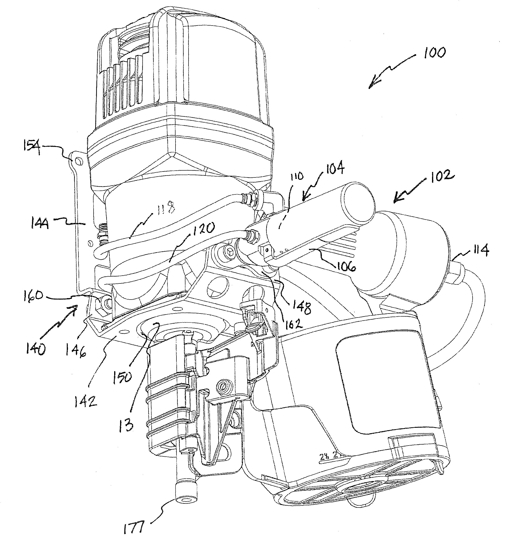
[0047]Referring now more particularly to the drawings, a pneumatically operated fastening tool, generally indicated at 10, is shown in FIG. 3, which embodies the principles of the present invention. The tool 10 includes a housing assembly, generally indicated at 12, which includes a main handle 102 of hollow configuration which constitutes a tool reservoir 103 for supply air under pressure coming from a source which is communicated therewith. The housing assembly 12 further includes a nose piece 17 defining a fastener drive track 18 adapted to receive laterally therein a leading fastener 19 from a package of fasteners mounted within a fastener magazine, generally indicated at 20. The magazine 20 is of conventional construction and operation. A feed pawl 14 is provided to pull successive nails from the magazine forward towa...


PUM

PropertyMeasurementUnit
weightaaaaaaaaaa
forceaaaaaaaaaa
air flow rateaaaaaaaaaa

Abstract

A fastening tool having plural power source ports that, when contemporaneously activated, deliver compressed air to a fastener driving assembly to drive a fastener into a workpiece.

Description

CROSS REFERENCE TO RELATED APPLICATION[0001]The present application claims priority under 35 U.S.C. §119 to U.S. Provisional Application Ser. No. 61 / 606,145 filed on Mar. 2, 2012, which is herein incorporated by reference in its entirety.BACKGROUND OF THE INVENTION[0002]1. Field of the Invention[0003]The present invention relates, in general, to the field of fastening tools. In particular, the present invention relates to fastening tools having plural sources of power channeled through plural handles, and more particularly to a fastening tool for industrial applications such as the manufacture of pallets, used in the shipping and handling of commercial of goods.[0004]Pallets are constructed by assembling wood boards in the form of a frame having at least one, and normally two, supporting surfaces or platforms which are spaced by beams or runners which extend perpendicular to the supporting surfaces in spaced relation. In the manufacture of wooden pallets, the boards which form the s...

Claims


Application Information

Patent Timeline
Patent Type & Authority Patents(United States)
IPC IPC(8): B25C1/04B25F5/02
CPCB25C1/04B25F5/026
Inventor STAPLES, KEVINPAIELLA, LUIGI ARNALDOSCABIN, GIANPAOLOMILLER, KEVEN E.LIU, I-HUI
Owner STANLEY FASTENING SYST LP
Why Eureka
Try Eureka