Device and method for adaptive ultrasound sensing

a technology of adaptive ultrasound and sensing device, applied in the direction of door/window fitting, using reradiation, instruments, etc., can solve the problems of low reliability, unsuitable for many applications, and prone to wear and tear of the instrument, so as to improve the device and the method of ultrasound sensing

Active Publication Date: 2006-10-31
GAL ELI +1
View PDF24 Cites 13 Cited by
  • Summary
  • Abstract
  • Description
  • Claims
  • Application Information

AI Technical Summary

Benefits of technology

[0015]An object of the present invention is therefore to provide improved device and method for ultrasound sensing.
[0040]The present invention is suitable for using, for example, with automatic doors, where it allows providing a secure and efficient sensing system, which maximizes sensing efficiency while minimizing the risk of injury to users.
[0041]The use of an adaptive ultrasound sensing system and method allows locating the sensor at different location without requiring a new calibration thereof, since the sensor learns the clutter dynamically and the detection thresholds are being built accordingly without being dependent on the environment in which the sensor is located.
[0042]In addition, the dynamic learning allows coping with the temperature, moisture, and wind changes.

Problems solved by technology

Tactile detectors are prone to suffer from a high degree of tear and ware and thus have a very low reliability.
Furthermore they require physical contact and more specifically that a minimum force be applied thereon to be tripped, which makes them unsuitable for many applications.
Optical sensors are sensitive to lighting conditions and do not function under daylight.
Moreover, they do not allow differentiating between objects at a close proximity since such differentiation requires a measurement capability in the magnitude of the speed of light for small divergences.
A common problem with ultrasonic sensors from the prior art is that they do not allow covering a volume where the signal fades and varies along the path and differentiating a legitimate clutter signal from a penetration signal.
A drawback of sensing methods and apparatuses from the prior art is that they do not allow discriminating between static objects and relevant targets to be detected.

Method used


Image

  • Device and method for adaptive ultrasound sensing
  • Device and method for adaptive ultrasound sensing
  • Device and method for adaptive ultrasound sensing

Examples


Embodiment Construction

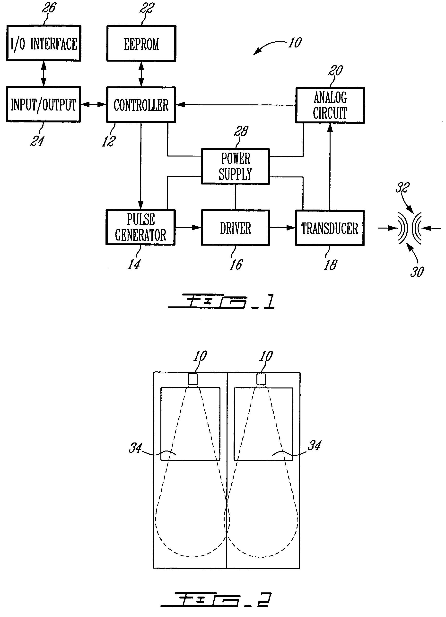
[0049]Turning now to FIG. 1 of the appended drawings, an adaptive ultrasound detecting system 10 according to an illustrative embodiment of the present invention will be described.

[0050]The detecting system 10 comprises a controller 12, a pulse generator 14 coupled to the controller 12, a sensor driver 16 coupled to the pulse generator 14, a transducer 18 coupled to the driver 16, an analog circuit 20 coupled to both the transducer 18 and to the controller 12, a memory means in the from of an EEPROM (Electrically Erasable Programmable Read Only Memory) 22 coupled to the controller 12, input / output (I / O) means 24, and an I / O interface coupled to the I / O means 24. The controller 12, pulse generator 14, sensor driver 16, transducer 18, and analog circuit 20 are connected to a power supply 28, in the form of a 12–24 DC (Direct Current) voltage source. Of course, the power supply 28 may take other forms allowing energizing the system 10.

[0051]The pulse generator 14 includes an oscillatin...


PUM


Abstract

The adaptive system and method for ultrasound sensing comprises re-evaluating over time the detection threshold for predetermined sensing positions along the scanning direction to cope for the static target and environment changes at the sensing positions. The method includes comparing the measured echo value at each sensing position to a reference echo value corresponding to the same sensing position, and to iteratively determine a new reference value whenever the echo value is greater than the reference echo value and that the difference between the measured echo value and the reference echo value is lower than a detection assurance factor. The use of the adaptive ultrasound sensing system and method allows locating the sensor at different location without requiring a new calibration thereof, since the sensor learns the clutter dynamically and the detection thresholds are being built accordingly without being dependent on the environment in which the sensor is located.

Description

[0001]This application claims the benifit of Provisional Application No. 60 / 436,455, filed Dec. 27, 2002.FIELD OF THE INVENTION[0002]The present invention relates to ultrasound sensing devices. More specifically, the present invention is concerned with a method and device for adaptive ultrasound sensing which finds applications, for example, in automatic door apparatus, bus and train doors safety sensors, machine tools, automatic self checkout systems, security sensors for valuables, and various proximity sensing systems.BACKGROUND OF THE INVENTION[0003]Automatic doors are in widespread use in various applications, such as elevators, buses, and trains. Considerations of personal safety require that doors are not to be closed when there is a danger that a person might be impacted thereby. While not compromising safety considerations, considerations of efficiency dictate that doors must be closed as promptly and quickly as possible. At the same time it is important that sensors, causi...

Claims


Application Information

Patent Timeline
Patent Type & Authority Patents(United States)
IPC IPC(8): G01S15/00E05F15/70G01S7/52G01S15/04G06F19/00
CPCG01S7/52004G01S15/04E05F2015/763E05F15/73Y10S367/909
Inventor GAL, ELIAGAM, URI
Owner GAL ELI
Why Eureka
Try Eureka