Edge-lit light fixture incorporating a downlight and having a uniform external appearance

a technology of downlight and light fixture, which is applied in the direction of lighting and heating apparatus, light source combinations, instruments, etc., can solve the problems of unfavorable aesthetics, unwieldy use of separate fixtures, and only diffuse light from the edge-lit panel

Inactive Publication Date: 2012-12-20
OSRAM SYLVANIA INC
View PDF14 Cites 86 Cited by
  • Summary
  • Abstract
  • Description
  • Claims
  • Application Information

AI Technical Summary

Benefits of technology

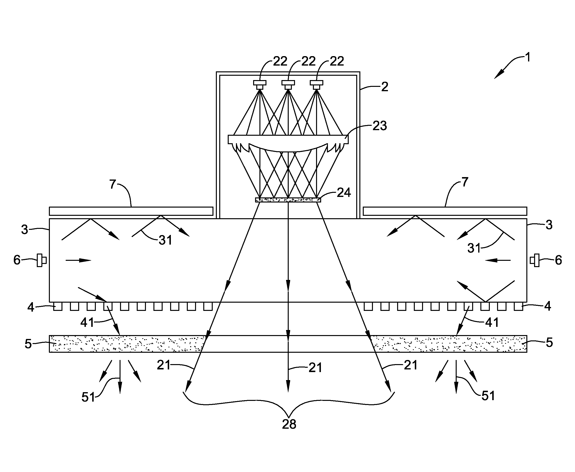
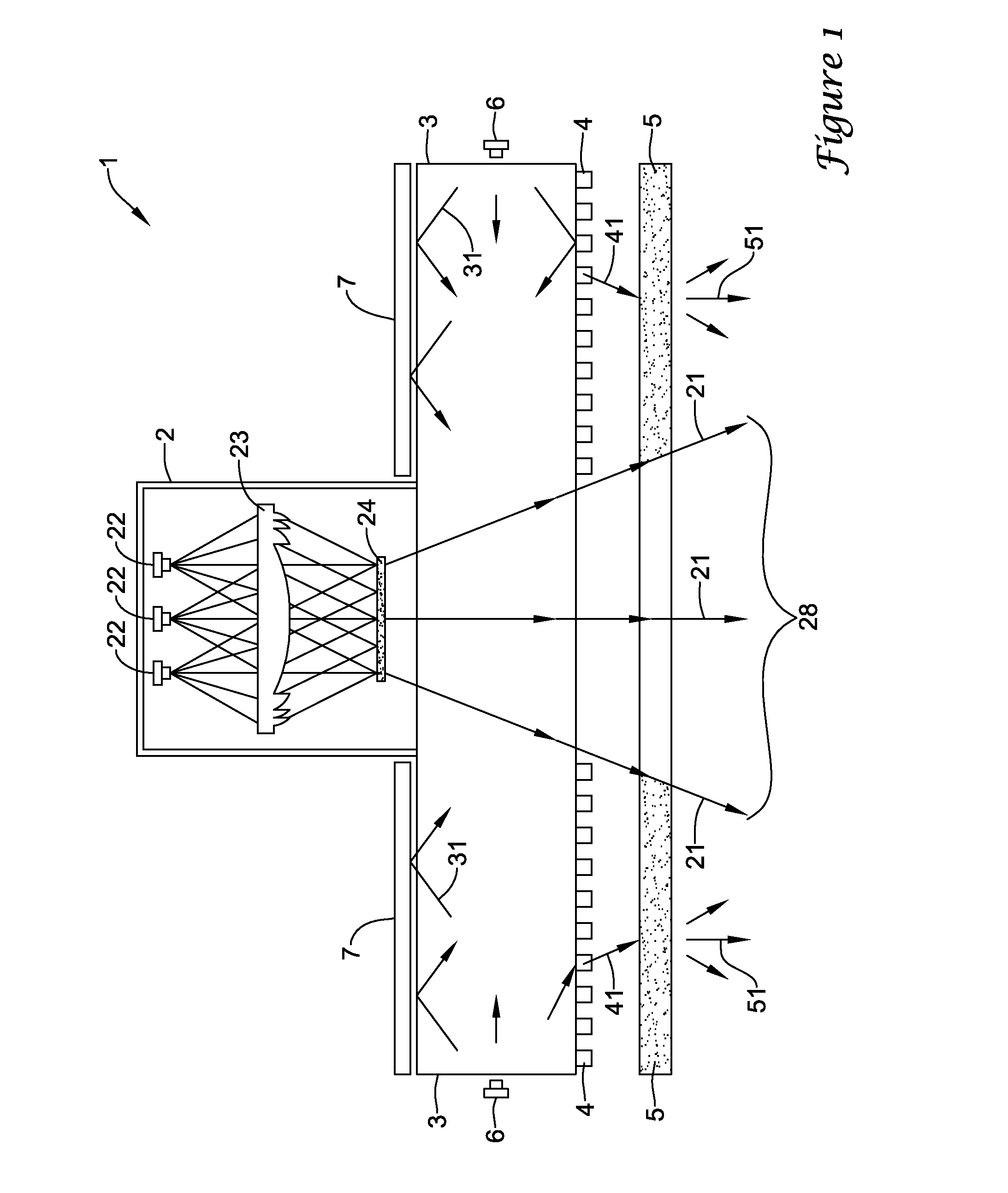
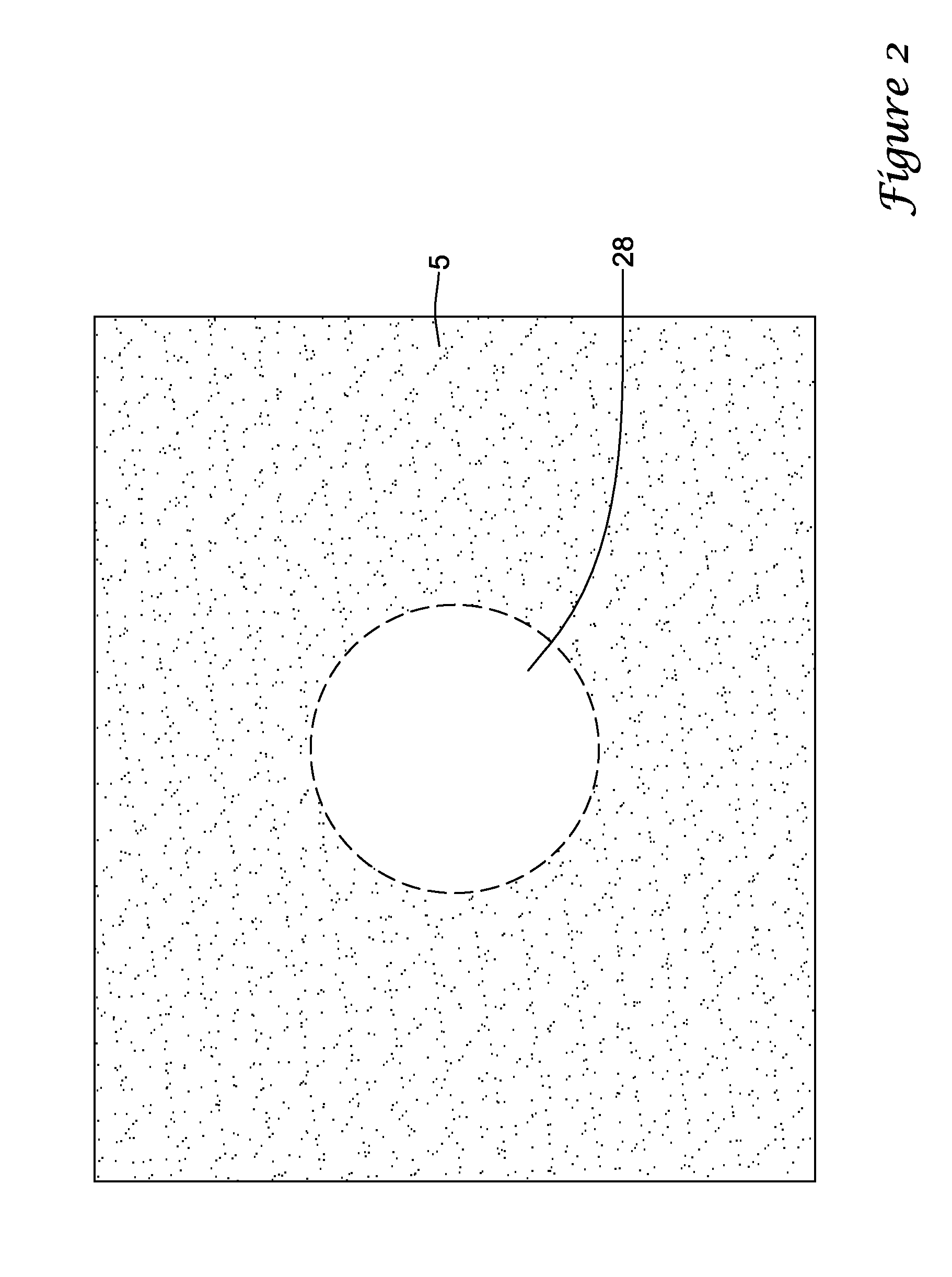
[0007]Another embodiment is a light fixture for producing downward-propagating illumination. The fixture includes an edge-lit lightguide. A downlight is disposed adjacent to a top face of the lightguide for directing directional light through the lightguide and out a bottom face of the lightguide. The directional light has a downlight beam footprint. A plurality of peripheral LEDs are disposed around a perimeter of the lightguide for emitting light into the lightguide. A light extractor is coupled to the lightguide for directing light out of the lightguide to form extracted light. The extractor area excludes the downlight beam footprint. A diffuser is longitudinally adjacent to the bottom face of the lightguide. The diffuser receives extracted light from the light extractor and transmits diffuse light out of the light fixture. The directional light has a more narrow angular spread than the diffuse light. The directional light has the same spectral profile as the diffuse light.

Problems solved by technology

While edge-lit panels tend to have a pleasing, uniform external appearance, such edge-lit panels tend to produce only diffuse light.
Use of a separate fixture is unwieldy, and may not be aesthetically pleasing.
These attempts may have produced both the diffuse light and the directional beam, but they lacked the pleasing, uniform external appearance of the uncut edge-lit panel.

Method used


Image

  • Edge-lit light fixture incorporating a downlight and having a uniform external appearance
  • Edge-lit light fixture incorporating a downlight and having a uniform external appearance
  • Edge-lit light fixture incorporating a downlight and having a uniform external appearance

Examples


Embodiment Construction

[0015]In this document, the directional terms “up”, “down”, “top”, “bottom”, “side”, “lateral”, “longitudinal” and the like are used to describe the absolute and relative orientations of particular elements. For these descriptions, it is assumed that the light fixture is mounted overhead, such as being incorporated into a ceiling tile or ceiling grid, and that the light fixture directs its output generally downward toward a user. It will be understood that while such descriptions provide orientations that occur in typical use, other orientations are certainly possible. For instance, the fixture may be wall-mounted or incorporated into additional elements to provide indirect lighting. The noted descriptive terms, as used herein, still apply to the fixture, even if the fixture has an orientation other than overhead, or is uninstalled in its overhead orientation.

[0016]A light fixture and method for producing downward-propagating illumination are disclosed. The fixture includes an edge-...


PUM


Abstract

A light fixture and method for producing downward-propagating illumination are disclosed. The fixture includes an edge-lit lightguide illuminated from its perimeter. The lightguide has a light extractor, such as a dot pattern on its bottom surface, which extracts a portion of the light from inside the lightguide and directs it to a diffuser. The diffuser randomizes the direction of the extracted light and forms diffuse light. The fixture also includes a downlight, arranged above the lightguide and producing a downlight beam downward. The downlight beam transmits from the top face through the bottom face of the lightguide and emerges from the bottom face of the lightguide as a directional beam. The downlight beam has a downlight beam footprint. The light extractor has a light extractor area that excludes the downlight beam footprint, and the diffuser has a diffuser area that also excludes the downlight beam footprint. The fixture can produce both diffuse light and a directional beam, while maintaining a generally uniform external appearance.

Description

TECHNICAL FIELD[0001]The present invention relates to edge-lit light fixtures that produce both diffuse light and a directional beam, while maintaining a uniform external appearance.BACKGROUND OF THE INVENTION[0002]Light emitting diodes (LEDs) are become more commonplace in general illumination applications, such as office spaces and conference rooms. For example, an edge-lit panel uses LEDs at its light source, and is become increasingly common for ceiling-based applications, such as incorporation into ceiling tiles. While edge-lit panels tend to have a pleasing, uniform external appearance, such edge-lit panels tend to produce only diffuse light.[0003]There are some instances where a user may want to use an additional directional beam, such as a spotlight or accent light, for illuminating a particular task or space. Typically, the user has to install a separate fixture that provides such a directional beam, often referred to as a downlight. Use of a separate fixture is unwieldy, a...

Claims


Application Information

Patent Timeline
Patent Type & Authority Applications(United States)
IPC IPC(8): F21V7/22
CPCF21S8/04G02B6/003G02B6/0035G02B6/0051F21Y2113/20F21Y2115/10
Inventor QUILICI, MICHAELDAVEY, JR., ERNEST
Owner OSRAM SYLVANIA INC
Why Eureka
Try Eureka