Vehicle parking assist system, vehicle including the same, and vehicle parking assist method

a technology for parking assistance and vehicles, applied in the direction of electric devices, process and machine control, rail devices, etc., can solve the problems of not taking into account the described technology, unintentional contact of vehicles, and vehicle position deviation, and achieve the effect of reducing the positional deviation from the parking position

Active Publication Date: 2012-12-20
TOYOTA JIDOSHA KK
View PDF4 Cites 40 Cited by
  • Summary
  • Abstract
  • Description
  • Claims
  • Application Information

AI Technical Summary

Benefits of technology

[0007]The invention provides a vehicle parking assist system and method, with which it is possible to minimize the positional deviation from the parking position, at which the vehicle is to be stopped, and provides a vehicle including the vehicle parking assist system.
[0023]According to the invention, during a vehicle parking assist operation, even after the vehicle comes close to the parking position, the vehicle is accurately guided and the overrun is monitored and prevented, so that it is possible to minimize the positional deviation from the parking position, at which the vehicle is to be stopped.

Problems solved by technology

However, the technologies described in JP-A-2007-97345 do not take into consideration the fact that the indicator of the electric power transmitting unit becomes positioned in the blind spot of the back monitor camera.
In particular, unless an overrun of the vehicle is prevented when the vehicle is approaching the electric power transmitting unit, a situation can occur, in which the vehicle is unintentionally brought into contact with the electric power transmitting unit etc.
On the other hand, when the vehicle is caused to stop well before the electric power transmitting unit to avoid the overrun, a situation can occur, in which the position of the vehicle is not appropriate to perform charging.

Method used


Image

  • Vehicle parking assist system, vehicle including the same, and vehicle parking assist method
  • Vehicle parking assist system, vehicle including the same, and vehicle parking assist method
  • Vehicle parking assist system, vehicle including the same, and vehicle parking assist method

Examples


Embodiment Construction

[0039]An embodiment of the invention will be described in detail below with reference to drawings. Note that the same or corresponding portions in the drawings are designated by the same reference numeral and the description thereof is not repeated.

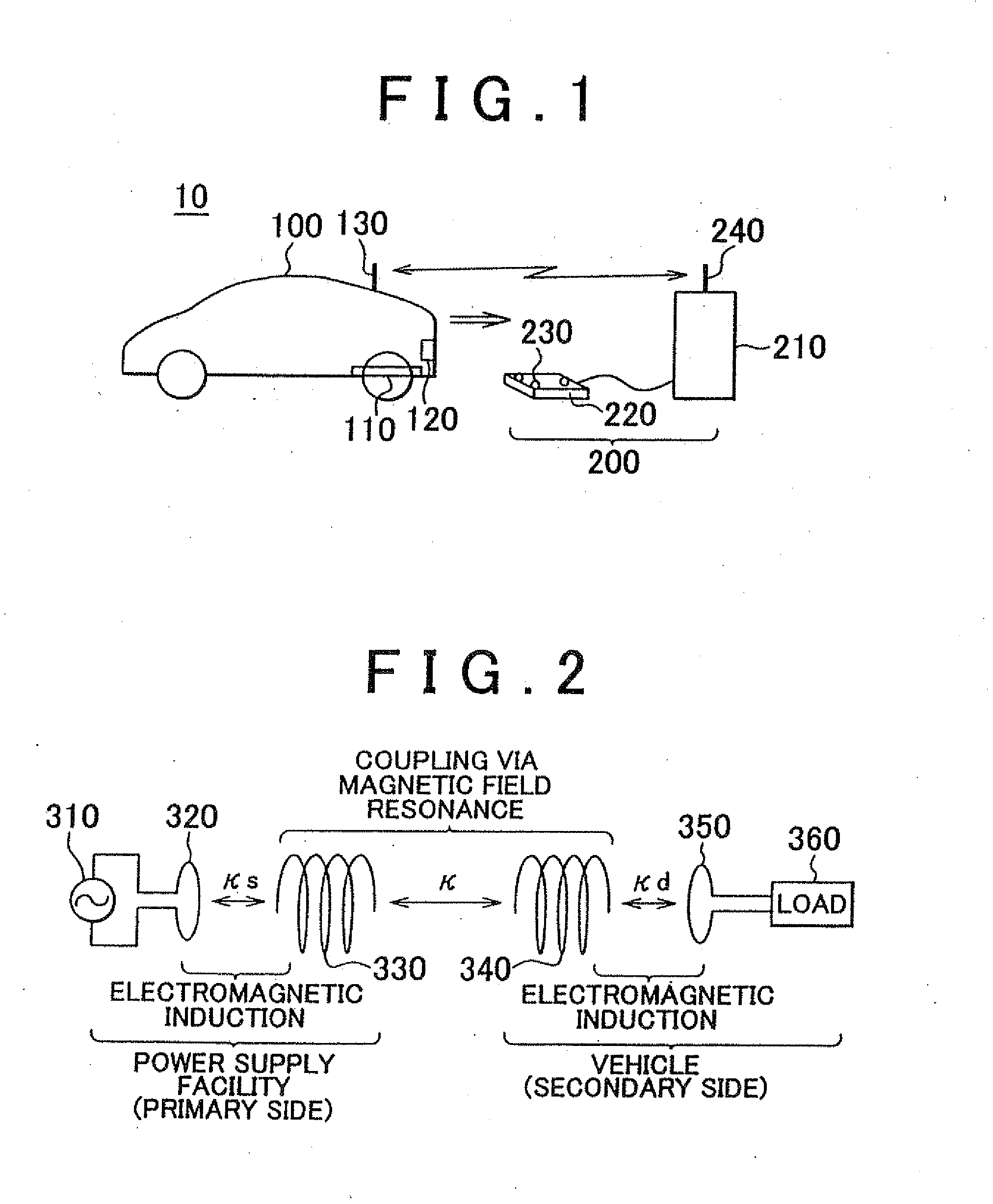
[0040]FIG. 1 is an overall configuration diagram of a vehicle power supply system according to the embodiment of the invention. Referring to FIG. 1, the vehicle power supply system 10 includes a vehicle 100 and a power supply apparatus 200. The vehicle 100 includes an electric power receiving unit 110, a camera 120, and a communication unit 130.

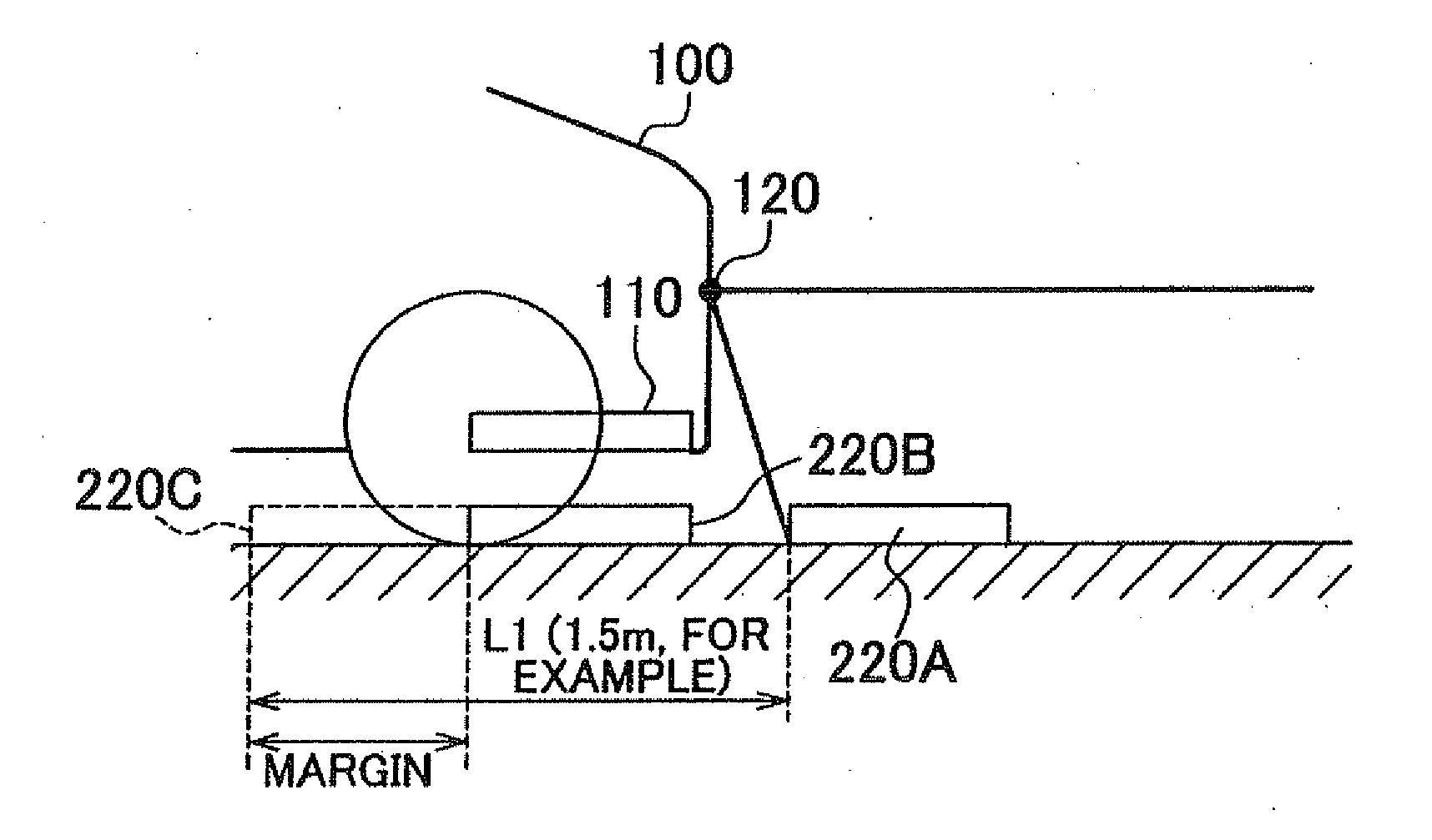
[0041]The electric power receiving unit 110 is installed at the bottom of a vehicle body and is configured to receive, in a non-contact manner, electric power sent from an electric power transmitting unit 220 of the power supply apparatus 200. More specifically, the electric power receiving unit 110 includes a self-resonant coil to be described later, and receives, in a non-contact manner, electric...


PUM


Abstract

A vehicle parking assist system includes: a camera; a first vehicle guiding section that recognizes the position of a power transmitter external to a vehicle based on the image obtained via the camera to guide the vehicle to the power transmitter; a power receiver that receives electric power from the power transmitter in a non-contact manner; and a second vehicle guiding section that guides the vehicle based on the electric power received by the power receiver. The control section executes a process of stopping the vehicle when the electric power received by the power receiver from the power transmitter does not satisfy a first condition, even after the control section has caused the vehicle driving section to move the vehicle beyond a predetermined distance after the first vehicle guiding section becomes unable to detect the position of the power transmitter based on the image.

Description

BACKGROUND OF THE INVENTION[0001]1. Field of the Invention[0002]The invention relates to a vehicle parking assist system, a vehicle including the vehicle parking assist system, and a vehicle parking assist method and in particular, to a vehicle parking assist system and method that perform a parking assist operation with the use of an electric power receiving section that receives electric power in a non-contact manner, and to a vehicle including the vehicle parking assist system.[0003]2. Description of the Related Art[0004]Vehicles, such as pure electric vehicles and plug-in hybrid vehicles, that are configured to be able to charge an electricity storage device on the vehicle from an external power source are in actual use. Technologies for automatically charging and technologies for guiding the vehicle for this purpose are being studied.[0005]Japanese Patent Application Publication No. 2007-97345 (JP-A-2007-97345) describes a technology for performing the alignment assist control,...

Claims


Application Information

Patent Timeline
Patent Type & Authority Applications(United States)
IPC IPC(8): G05D1/02B60L11/18H04N7/18B60L5/00B60L50/15B60L50/16B60M7/00
CPCB60L2220/14B60L53/60G05D1/0246G05D2201/0213Y02T10/6217Y02T10/7005Y02T10/7077Y02T90/122Y02T90/128Y02T90/14Y02T90/163Y02T90/121Y02T10/7072Y02T10/7258B60L50/61B60L50/16B60L53/12G05D1/0225B60L53/62B60L53/126Y02T10/62Y02T10/72Y02T10/70Y02T90/12B60W30/06B62D15/02G05D1/02Y02T90/16
Inventor NAKAMURA, TORUICHIKAWA, SHINJI
Owner TOYOTA JIDOSHA KK
Why Eureka
Try Eureka