Disassembly device

Inactive Publication Date: 2012-12-27
HONG FU JIN PRECISION IND (SHENZHEN) CO LTD +1
2 Cites 1 Cited by

AI-Extracted Technical Summary

Problems solved by technology

Because the upper cover and the lower cover are fixed to other members of the electronic device, an ...

Abstract

A disassembling device includes a plate, a number of suction cups, a number of fasteners, and a number of rods. The suction cups and the fasteners are respectively disposed at opposite sides of the plate to the fasteners. The plate includes a number of through holes. Each of the rods is fixed to one of the suction cups, the rods extend through the respective through holes, and is connected to the respective fasteners.

Application Domain

Work holdersMetal working apparatus

Technology Topic

FastenerEngineering

Image

  • Disassembly device
  • Disassembly device
  • Disassembly device

Examples

  • Experimental program(1)

Example

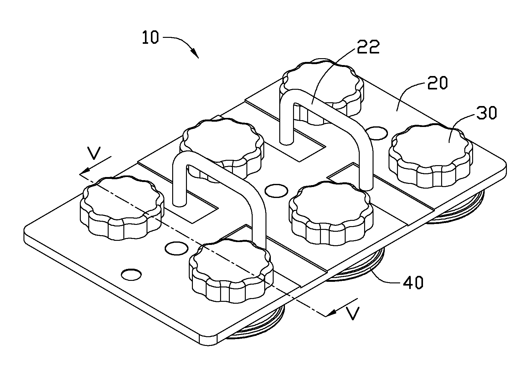
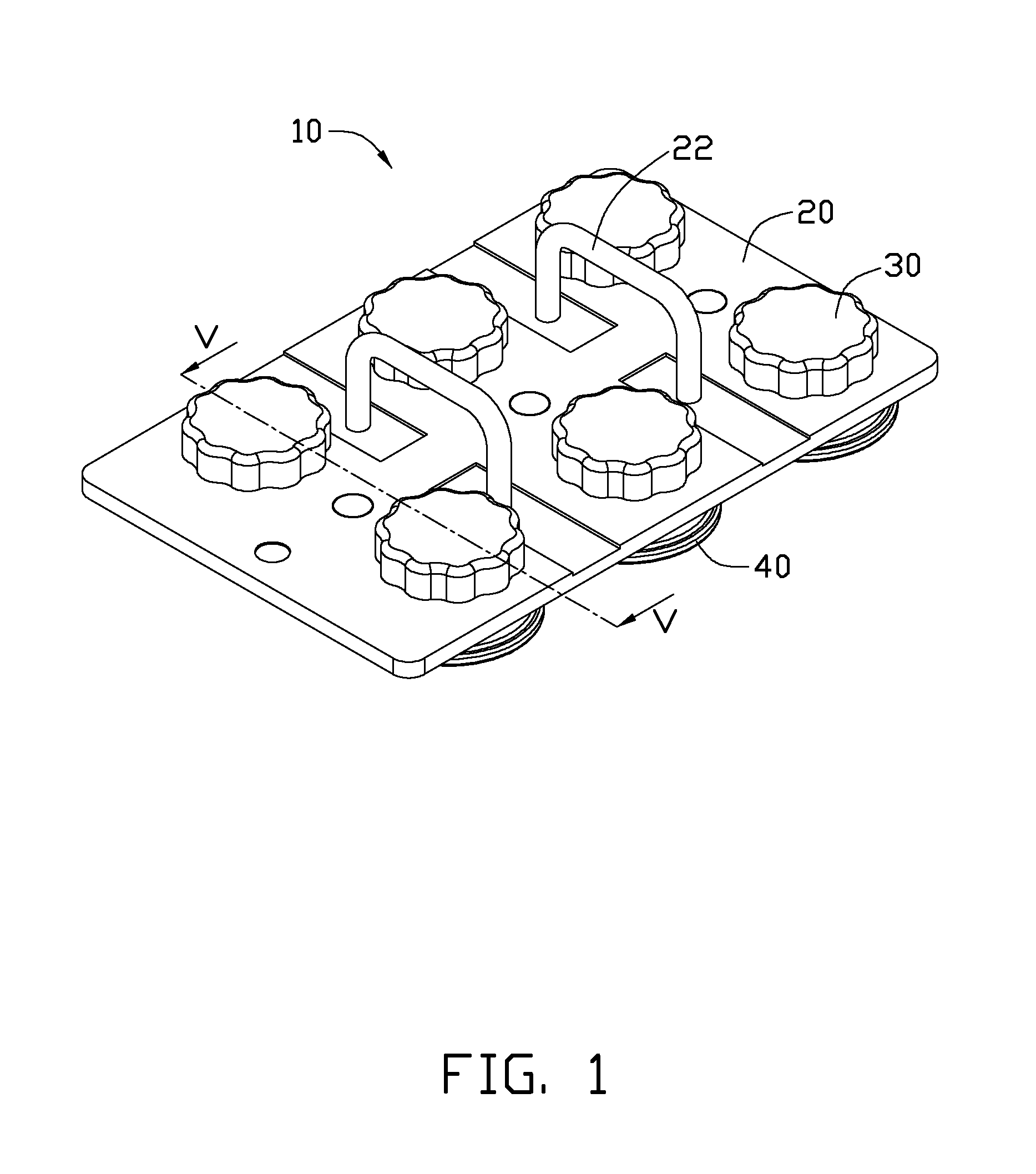
[0011]Referring to FIGS. 1 and 2, a disassembly device 10 according to an exemplary embodiment includes a plate 20, a number of fasteners 30, and a number of suction cups 40. The fasteners 30 and the suction cups 40 are respectively disposed at opposite sides of the plate 20. The plate 20 includes a handle 22 that can be gripped by an operator to push or pull the disassembly device 10.
[0012]Referring to FIGS. 3 and 4, each suction cup 40 includes a seat 42 protruding from a back side of the suction cup 40. A rod 50 protrudes from the top of each seat 42. Each rod 50 includes an external thread formed on a lateral surface thereof. In the embodiment, the rod 50 is integrally formed on the suction cup 40 by double shot molding. Each fastener 30 includes a sleeve 32 defining a threaded hole. The plate 20 further defines a number of through holes 24.
[0013]Referring to FIG. 5, the distal end of each rod 50 passes through a corresponding through hole 24 of the plate 20 and is screwed into the threaded hole of the corresponding sleeve 32. The seats 42 and the fasteners 30 respectively abut against opposite sides of the plate 20. When disassembling a cover from an electronic device (not shown), the suction cups 40 are put on the cover and a pushing force is exerted on the handle 22. The suction cups 40 are then deformed and the air in the suction cups 40 is expelled. As a result, the suction cups 40 firmly attach to the cover under vacuum. An operator can then grip the handle 22 to pull the cover until the cover is detached.
[0014]It is to be understood, however, that even though numerous characteristics and advantages of the present disclosure have been set forth in the foregoing description, together with details of the structure and function of the present disclosure, the present disclosure is illustrative only, and changes may be made in detail, especially in matters of shape, size, and arrangement of parts within the principles of the present disclosure to the full extent indicated by the broad general meaning of the terms in which the appended claims are expressed.

PUM

no PUM

Description & Claims & Application Information

We can also present the details of the Description, Claims and Application information to help users get a comprehensive understanding of the technical details of the patent, such as background art, summary of invention, brief description of drawings, description of embodiments, and other original content. On the other hand, users can also determine the specific scope of protection of the technology through the list of claims; as well as understand the changes in the life cycle of the technology with the presentation of the patent timeline. Login to view more.
Why Eureka
Try Eureka