Swing gate for device lockout in a curved cutter stapler

a technology of curved cutter and lockout mechanism, which is applied in the direction of surgical staples, paper/cardboard containers, surgical forceps, etc., can solve the problems of no longer providing the user a visual indicator of a spent cartridge, no longer providing a strong lockout, and prior art lockout mechanisms that do not provide strong lockout, so as to prevent the use of the cartridge housing

Active Publication Date: 2010-01-05
ETHICON ENDO SURGERY INC
View PDF15 Cites 1564 Cited by
  • Summary
  • Abstract
  • Description
  • Claims
  • Application Information

AI Technical Summary

Benefits of technology

[0014]It is still another object of the present invention to provide a linear surgical stapler wherein the top surface includes a tab member shaped and dimensioned for engaging the firing mechanism in a manner preventing firing of the present linear surgical stapler.
[0018]It is a further object of the present invention to provide a linear surgical stapler wherein the swing gate tab moves between a first position substantially transverse to a longitudinal axis of the linear surgical stapler and a second position substantially parallel to the longitudinal axis of the linear surgical stapler, such that when the swing gate tab is in its first position it sits forward of an upper surface of the lockout lever and during firing of the surgical stapler device the swing gate tab is rotated to its second position substantially parallel to the longitudinal axis of the surgical stapler device and removed from the upper surface of the lockout lever permitting the lockout lever to move upwardly into a locked position.
[0019]It is also an object of the present invention to provide a linear surgical stapler wherein force from the firing mechanism rotates the swing gate tab with enough force to deflect the lockout lever downwardly into the recess and out of the way of the firing bar and movement of the swing gate tab continues to its second position substantially parallel to the longitudinal axis of the surgical stapling device where, and once the firing mechanism is retracted, the lockout lever returns to a blocking position preventing any further rotation of the swing gate and firing of the linear surgical stapler.
[0020]It is another object of the present invention to provide a linear surgical stapler which includes an anvil structure and a cartridge housing containing a plurality of surgical fasteners. The cartridge housing and anvil structure are relatively movable between a first spaced apart position and a second position in close approximation with one another. A firing mechanism is associated with the cartridge housing for ejecting the surgical fasteners from the cartridge housing to be driven against the anvil structure. A lockout mechanism interacts with the cartridge housing for selective activation and deactivation. The lockout mechanism includes a swing gate pivotally secured to the cartridge housing such that firing of the linear surgical stapler rotates the swing gate for preventing further firing of the used cartridge housing.
[0022]It is also an object of the present invention to provide a linear surgical stapler including a lock tab which prevents movement of the swing gate after rotation of the swing gate during firing.

Problems solved by technology

However, the lockout mechanism is designed such that the firing mechanism only works for a cartridge module that has not been previously used.
When a new cartridge module is loaded into the instrument, the location of the driver, as it relates to the cartridge module in the instrument, interferes with the lockout arm in a way so as to let the instrument fire staples.
In particular, prior art devices allow the driver to be pushed back in a manner which could result in turning off the lockout as they tend to be dependent upon the position of the driver in relation to the lockout mechanism.
These products, if the driver was pushed back far enough to visually hide the driver in the cartridge, would no longer provide the user a visual indicator of a spent cartridge.
In addition, some prior art lockout mechanisms do not provide a strong lockout due to the components interacting in creating the lockout after firing.

Method used


Image

  • Swing gate for device lockout in a curved cutter stapler
  • Swing gate for device lockout in a curved cutter stapler
  • Swing gate for device lockout in a curved cutter stapler

Examples


Embodiment Construction

[0033]The detailed embodiment of the present invention is disclosed herein. It should be understood, however, that the disclosed embodiment is merely exemplary of the invention, which may be embodied in various forms. Therefore, the details disclosed herein are not to be interpreted as limiting, but merely as the basis for the claims and as a basis for teaching one skilled in the art how to make and / or use the invention.

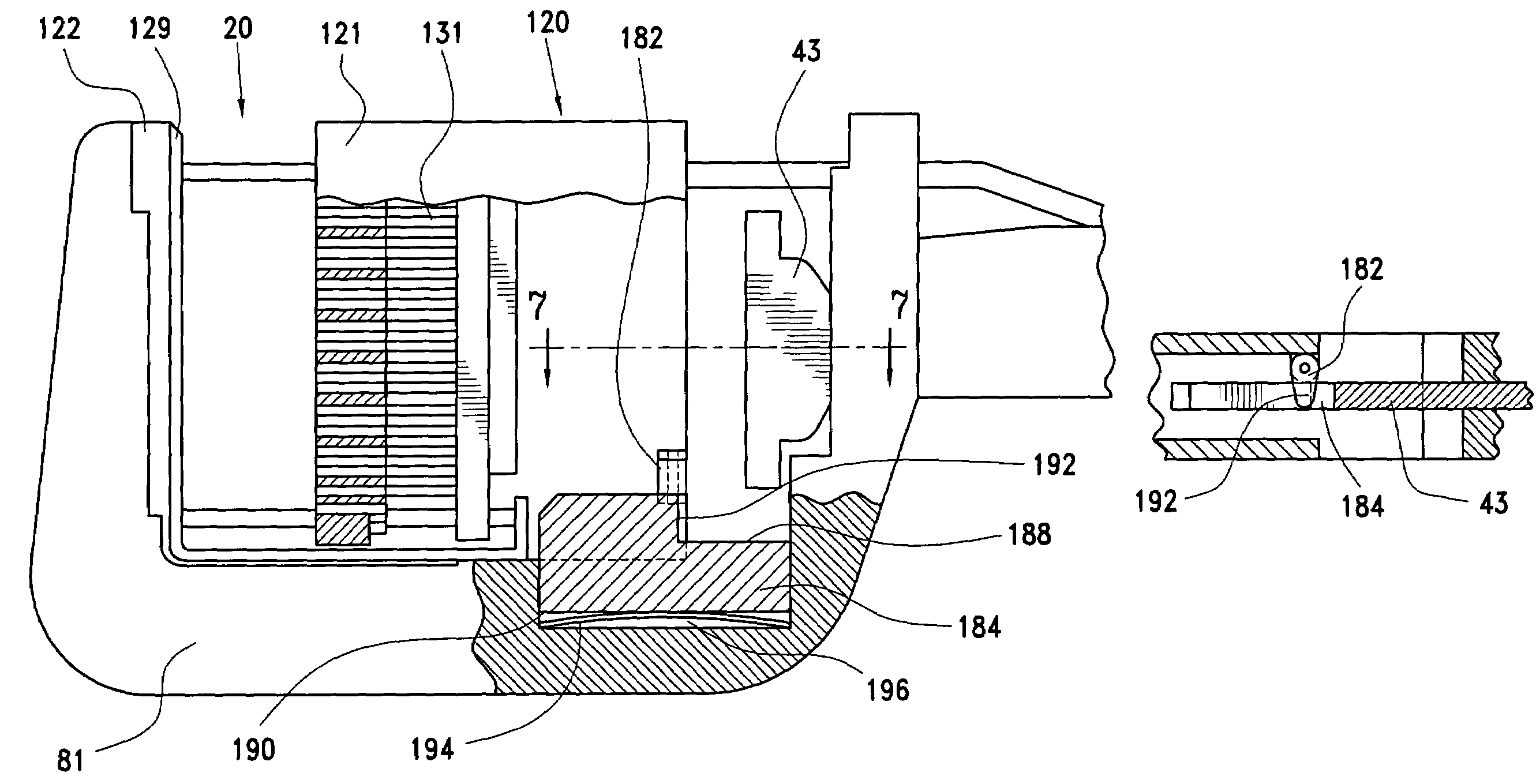
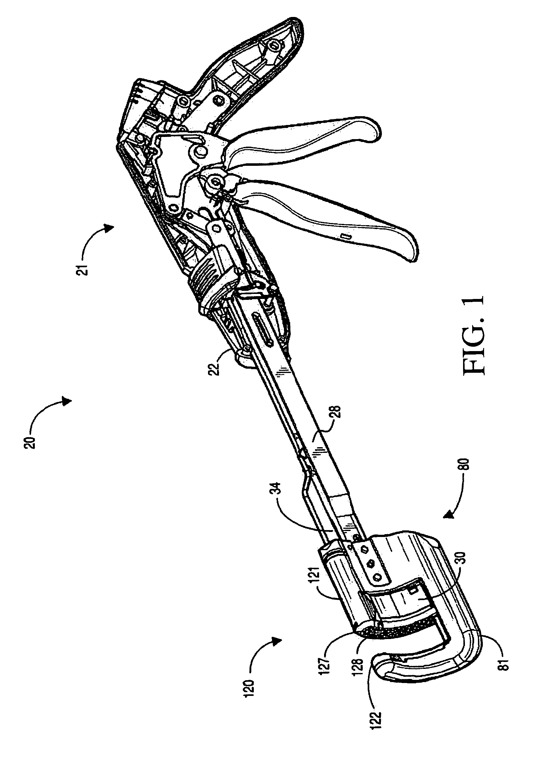
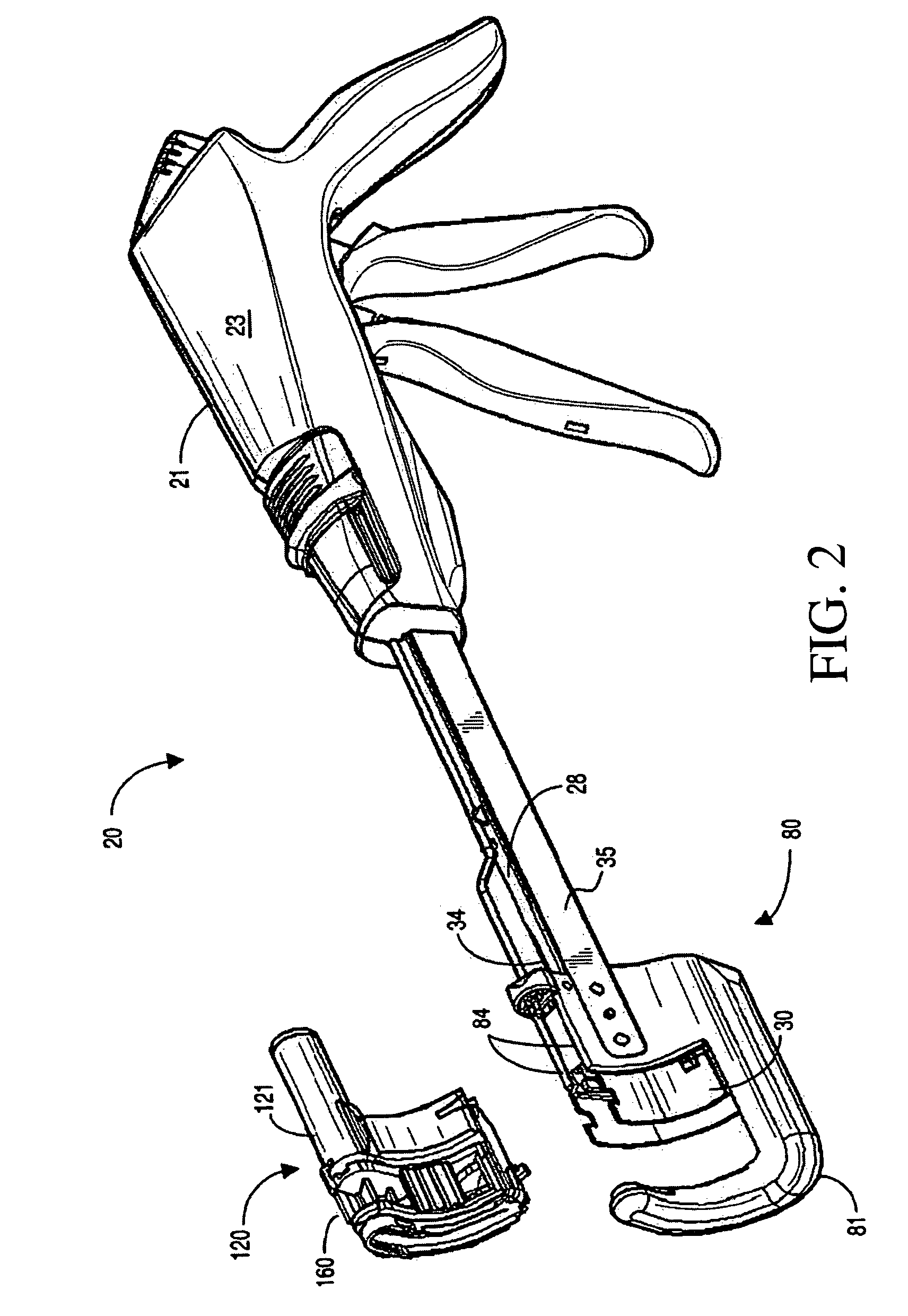
[0034]With reference to the various figures, a surgical instrument 20 adapted for applying a plurality of surgical fasteners to body tissue is disclosed. The surgical instrument 20 includes an anvil 122 and a cartridge housing 121 containing a plurality of surgical fasteners. The cartridge housing 121 and anvil 122 are relatively movable between a first spaced apart position and a second position in close approximation with one another. A firing mechanism is associated with the cartridge housing 121 for ejecting the surgical fasteners from the cartridge housing 121 t...


PUM

PropertyMeasurementUnit
forceaaaaaaaaaa
movementaaaaaaaaaa
rotationaaaaaaaaaa

Abstract

A linear surgical stapler adapted for applying a plurality of surgical fasteners to body tissue includes an anvil structure and a cartridge housing containing a plurality of surgical fasteners. The cartridge housing and anvil structure are relatively movable between a first spaced apart position and a second position in close approximation with one another. A firing mechanism is associated with the cartridge housing for ejecting the surgical fasteners from the cartridge housing to be driven against the anvil structure. A lockout mechanism interacts with the cartridge housing for selective activation and deactivation. The lockout mechanism includes a swing gate tab secured to the cartridge housing at a position adjacent a lockout lever, such that firing of the linear surgical stapler rotates the swing gate tab releasing the lockout lever for preventing further firing of the used cartridge housing.

Description

BACKGROUND OF THE INVENTION[0001]1. Field of the Invention[0002]The present invention relates to surgical stapling and cutting instruments adapted for use in the diagnosis and therapy of pathologies treated by stapled resection. More particularly, the invention relates to a lockout mechanism for utilization in conjunction with surgical stapling and cutting instruments.[0003]2. Description of the Prior Art[0004]Surgical stapling and cutting instruments are commonly utilized in the diagnosis and treatment of pathologies treated by stapled resection. Surgical stapling and cutting instruments provide a mechanism to extend the transluminal exploitation of mechanical suturing devices introduced via the anal canal, mouth, stomach and service accesses. Although surgical stapling and cutting instruments are most commonly utilized with rectal pathologies, surgical stapling and cutting instruments may be used in a variety of environments.[0005]Over time, surgical stapling and cutting instrumen...

Claims


Application Information

Patent Timeline
Patent Type & Authority Patents(United States)
IPC IPC(8): A61B17/10
CPCA61B17/072A61B2017/07214A61B2090/0814A61B2017/2945A61B2017/07221
Inventor KRUSZYNSKI, MICHAEL L.LUDZACK, MICHAEL R.KELLY, WILLIAM D.FLAXMAN, HOWARD N.
Owner ETHICON ENDO SURGERY INC
Why Eureka
Try Eureka