
Coated surgical staples and an illuminated staple cartridge for a surgical stapling instrument

a surgical stapling and illuminated technology, applied in the field of surgical staples, can solve the problems of affecting affecting and affecting the ability to evaluate the integrity of the staple line, so as to reduce the reflectivity of the surgical staple. , the effect of enhancing the visibility of the surgical staple within the tissu

Inactive Publication Date: 2011-06-07
COVIDIEN LP
View PDF25 Cites 1576 Cited by
  • Summary
  • Abstract
  • Description
  • Claims
  • Application Information

AI Technical Summary

Benefits of technology

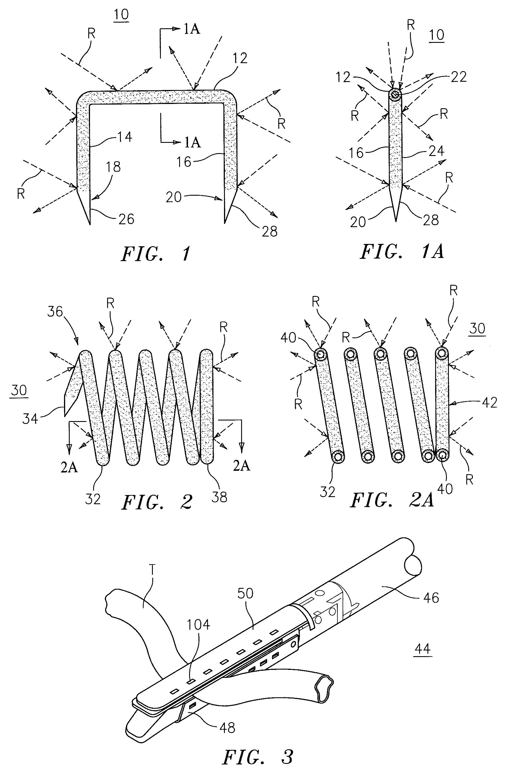
[0009]A surgical fastener is formed as a conventional U-shaped surgical staple having a backspan and a pair of legs extending distally from the backspan. Each of the legs terminates in a tissue penetrating tip. The surgical staple is coated with a material configured to enhance the visibility of the surgical staple within tissue while at the same time reducing the reflectivity of the surgical staple. In a specific embodiment, the tissue penetrating tips of the surgical staple are not coated so as to avoid blunting of the sharp tips.
[0010]In an alternative embodiment, the surgical fastener is formed as a helical coil fastener having a sharp distal tissue penetrating tip in a compressed proximal coil facilitating insertion in tissue. The disclosed helical coil fastener is coated to enhance visibility while reducing reflectivity.
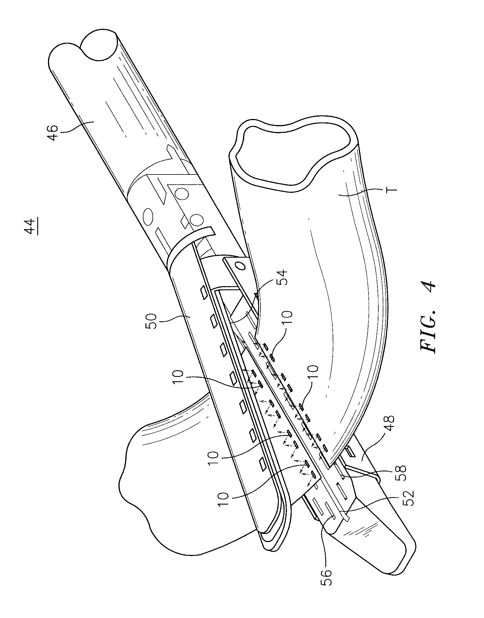
[0011]There is also disclosed a staple cartridge for use with a surgical stapling device having a light source. The staple cartridge generally includes a U-shaped outer channel member and a transparent insert positioned within the U-shaped outer channel member. The transparent insert includes a body portion having a tapered leading edge and an upwardly facing surface for emitting light. In a particular embodiment, the U-shaped outer channel is formed with a series of longitudinally extending windows allowing light transmitted through side surfaces of the transparent insert to pass there through. In use, the relative positioning of staple drivers and a knife blade, associated with a surgical stapling device, attenuate the amount of light passing through the transparent insert and out through the windows in the U-shaped outer channel. The sled or pushers will block any light for distal light windows until it progresses past, thus indicating staple line positional status.
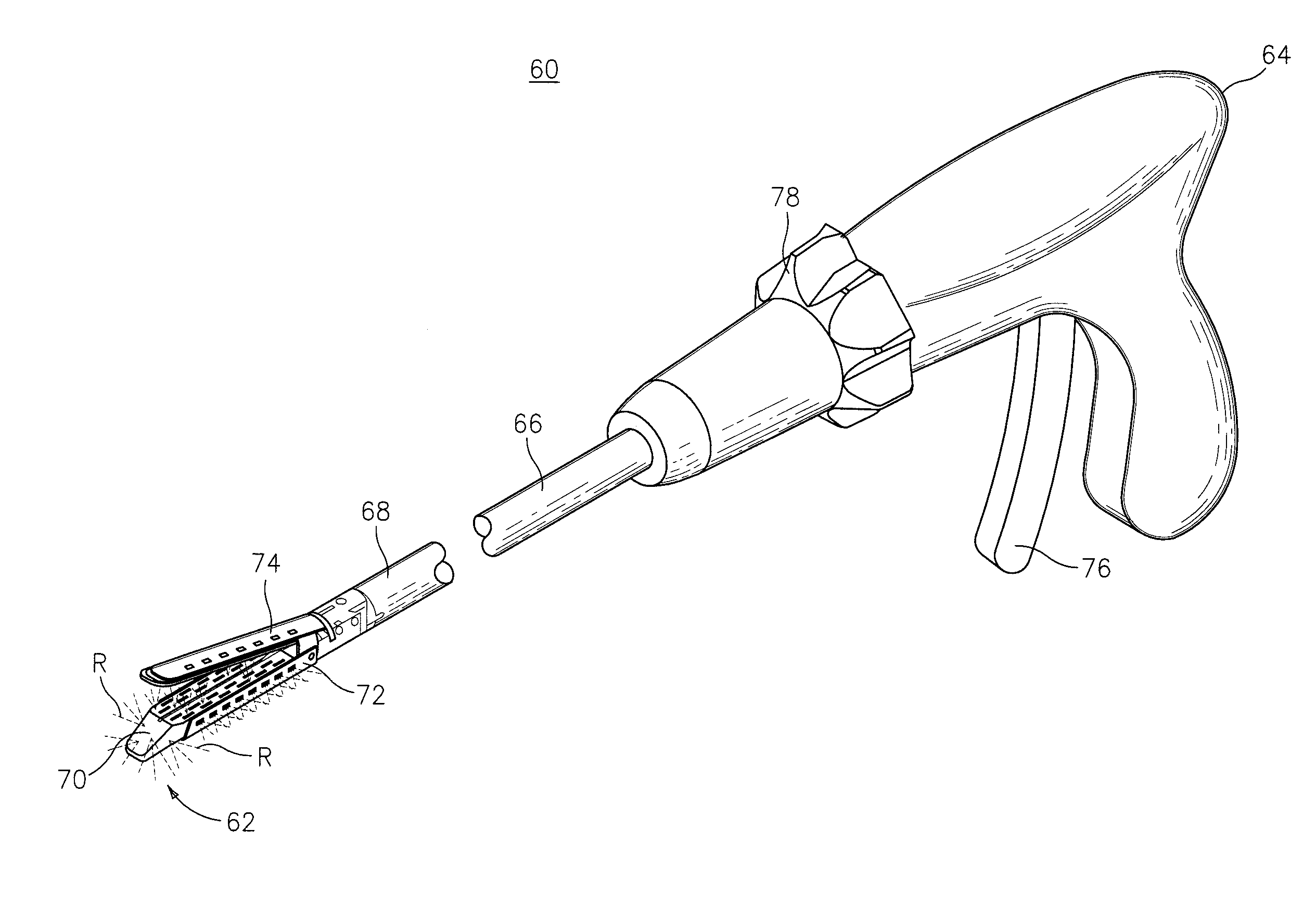
[0012]There is also disclosed a surgical stapling device having a staple cartridge to facilitate visual positioning of the distal end of the surgical stapling device within tissue. The staple cartridge is positioned on a distal end of the surgical stapling device such that a light source associated with the surgical stapling device is in position to transmit light to the transparent insert associated with the staple cartridge.

Problems solved by technology

The ability to visualize the distal end of the surgical stapling device is more difficult when the surgical stapling device is used endoscopically or laparoscopically.
This may make it difficult to verify that the surgical stapling device has functioned properly and to evaluate the integrity of the staple line formed by the surgical stapling device.
The ability to evaluate the integrity of the staple line may be hindered by the use of conventional staples formed of stainless steel and / or titanium as these materials tend to reflect light back towards the lens in the endoscope or laparoscope obscuring a clear view of the staple line.

Method used


Image

  • Coated surgical staples and an illuminated staple cartridge for a surgical stapling instrument
  • Coated surgical staples and an illuminated staple cartridge for a surgical stapling instrument
  • Coated surgical staples and an illuminated staple cartridge for a surgical stapling instrument

Examples


Embodiment Construction

[0026]Embodiments of the presently disclosed surgical fasteners and surgical stapling device will now be described in detail with reference to the drawings wherein like numerals designate identical or corresponding elements in each of the several views. As is common in the art, the term ‘proximal” refers to that part or component closer to the user or operator, i.e. surgeon or physician, while the term “distal” refers to that part or component further away from the user.

[0027]Referring to FIG. 1, there is disclosed a surgical fastener or surgical staple 10 which includes a coating, coloring or other material to assist in viewing the staple within the body of a patient and to assist in viewing the proper formation of staple 10 into the characteristic “B” fully formed shape. Staple 10 generally includes a backspan 12 having first and second legs14 and 16, respectively, extending distally from backspan 12. First leg 14 terminates in a tissue penetrating tip 18 and second leg 16 termina...


PUM

PropertyMeasurementUnit
molecular fluorescenceaaaaaaaaaa
molecular phosphorescenceaaaaaaaaaa
chemiluminescentaaaaaaaaaa

Abstract

A coated surgical fastener is provided for an easy visualization within tissue. The coated surgical fastener includes a core and a relatively non-reflective coating applied about the core. There is also disclosed an illuminated staple cartridge for use with a surgical stapling device having a light source. The illuminated staple cartridge includes a transparent insert and a relatively nontransparent U-shaped outer channel at least partially surrounding the transparent insert. Windows formed in sides of the U-shaped outer channel allow defined amounts of light to project from the sides of the illuminated staple cartridge.

Description

CROSS REFERENCE TO RELATED APPLICATIONS[0001]This application claims benefit of U.S. Provisional Application Ser. No. 60 / 985,661 filed Nov. 6, 2007, the disclosures of which are hereby incorporated by reference herein, in their entirety.BACKGROUND[0002]1. Technical Field[0003]The present disclosure relates to surgical staples for use in a surgical stapling instrument. More particularly, the present disclosure relates to surgical staples coated to enhance visibility of placement in tissue. The present disclosure further relates to a staple cartridge having internal illumination to enhance visibility of the cartridge's position in tissue and positioning of the internal components of the staple cartridge.[0004]2. Background of Related Art[0005]During certain surgical procedures various surgical stapling devices are used to apply one or more rows of staples to tissue and, in some cases, cut the tissue between the rows of staples. The visibility of the distal end of the stapling device u...

Claims


Application Information

Patent Timeline
Patent Type & Authority Patents(United States)
IPC IPC(8): A61B17/068
CPCA01H5/0222A61B17/064A61B17/07292A61B19/5202A61B19/54A61B2017/00907Y10S411/92A61B2017/0649A61B2019/4857A61B2019/5204A61B2019/5206A61B2019/5441A61B2017/00995A61B90/30A61B90/39A61B2090/0811A61B2090/304A61B2090/306A61B2090/3941A61B17/07207A61B2017/07271A01H6/749
Inventor ZEMLOK, MICHAELROSS, ADAM J.HATHAWAY, PETER
Owner COVIDIEN LP
Learn More