Auxiliary device for sliding module

Inactive Publication Date: 2012-12-27
FIRST DOME
14 Cites 4 Cited by

AI-Extracted Technical Summary

Problems solved by technology

However, these reference data are failed to physically teach or disclose that how to improve the conventional skills on decreasi...

Benefits of technology

[0010]Accordingly, the main purpose of the invention is to provide an auxiliary device for a sliding module. The auxiliary device includes a substrate having a guiding portion, a belt wheel rotatably disposed on the substrate, a wire disposed on the belt wheel, and a movable or sliding rack utilized for pivoting the wire. The s...

Abstract

An auxiliary device for a sliding module is disclosed. The auxiliary device includes a substrate having a guiding portion, a belt wheel rotatably disposed on the substrate, a wire disposed on the belt wheel, and a movable or sliding rack utilized for pivoting the wire. The sliding rack is movably attached to the guiding portion of the substrate and is capable of assembling with a sliding module. When the sliding rack driven by the sliding module is reciprocally moved, the sliding rack drives the wire to rotate the belt wheel, thus to minimize the unsmooth operation compared to conventional skills.

Application Domain

Digital data processing detailsGearing +1

Technology Topic

EngineeringMechanical engineering +1

Image

  • Auxiliary device for sliding module
  • Auxiliary device for sliding module
  • Auxiliary device for sliding module

Examples

  • Experimental program(1)

Example

[0019]The following description is of the best-contemplated mode of carrying out the invention. This description is made for the purpose of illustrating the general principles of the invention and should not be taken in a limiting sense. The scope of the invention is best determined by reference to the appended claims.
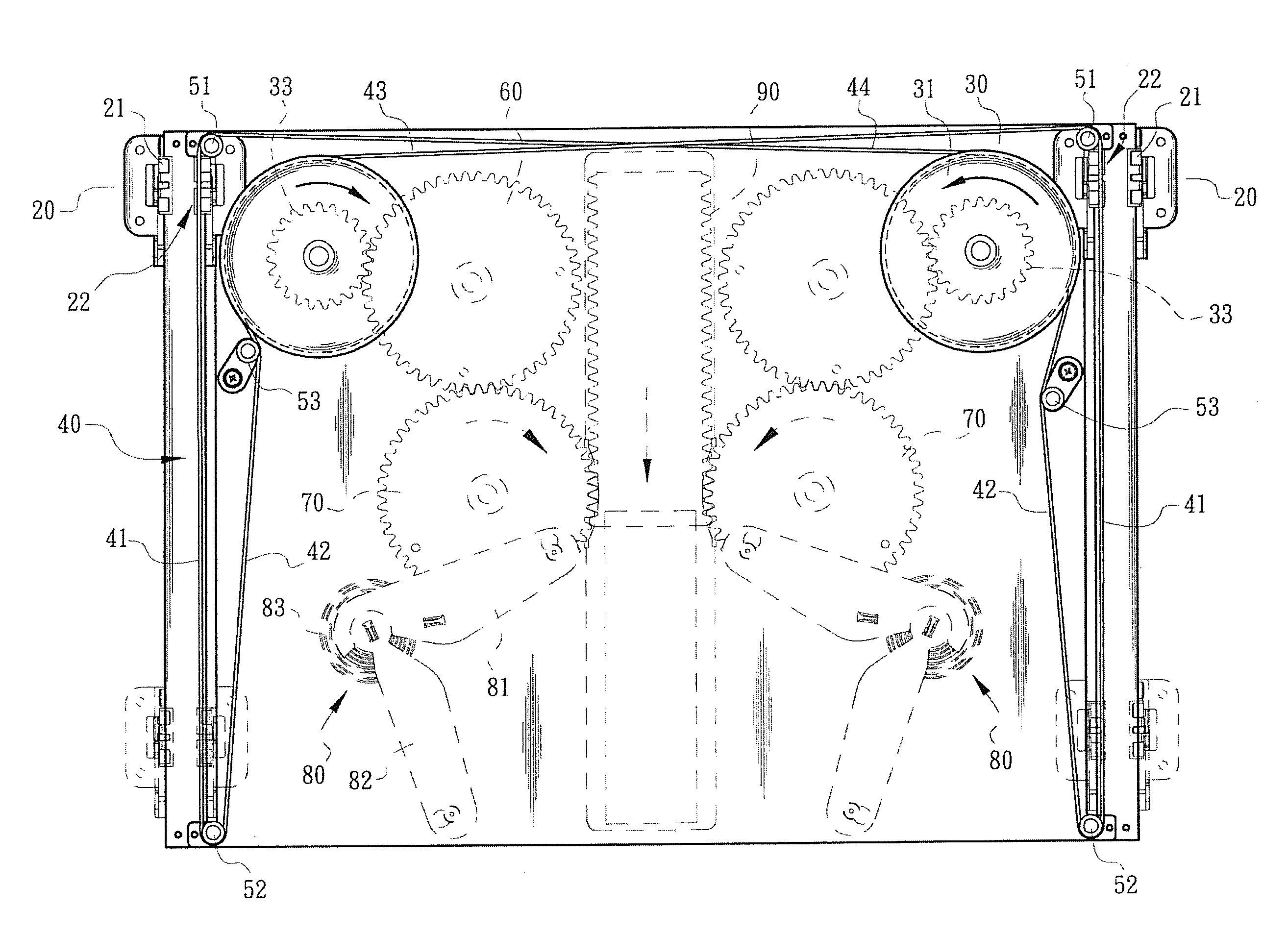
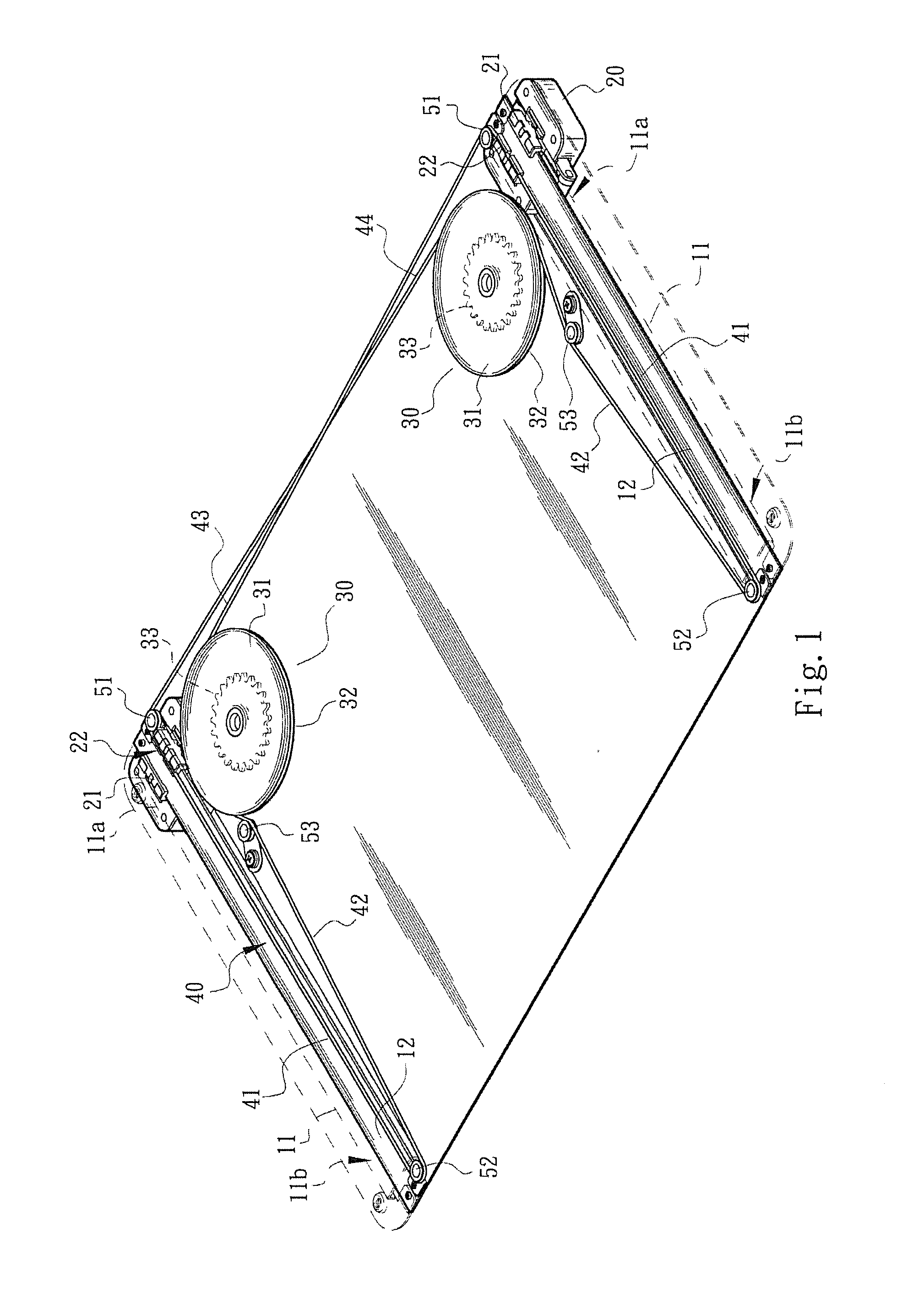
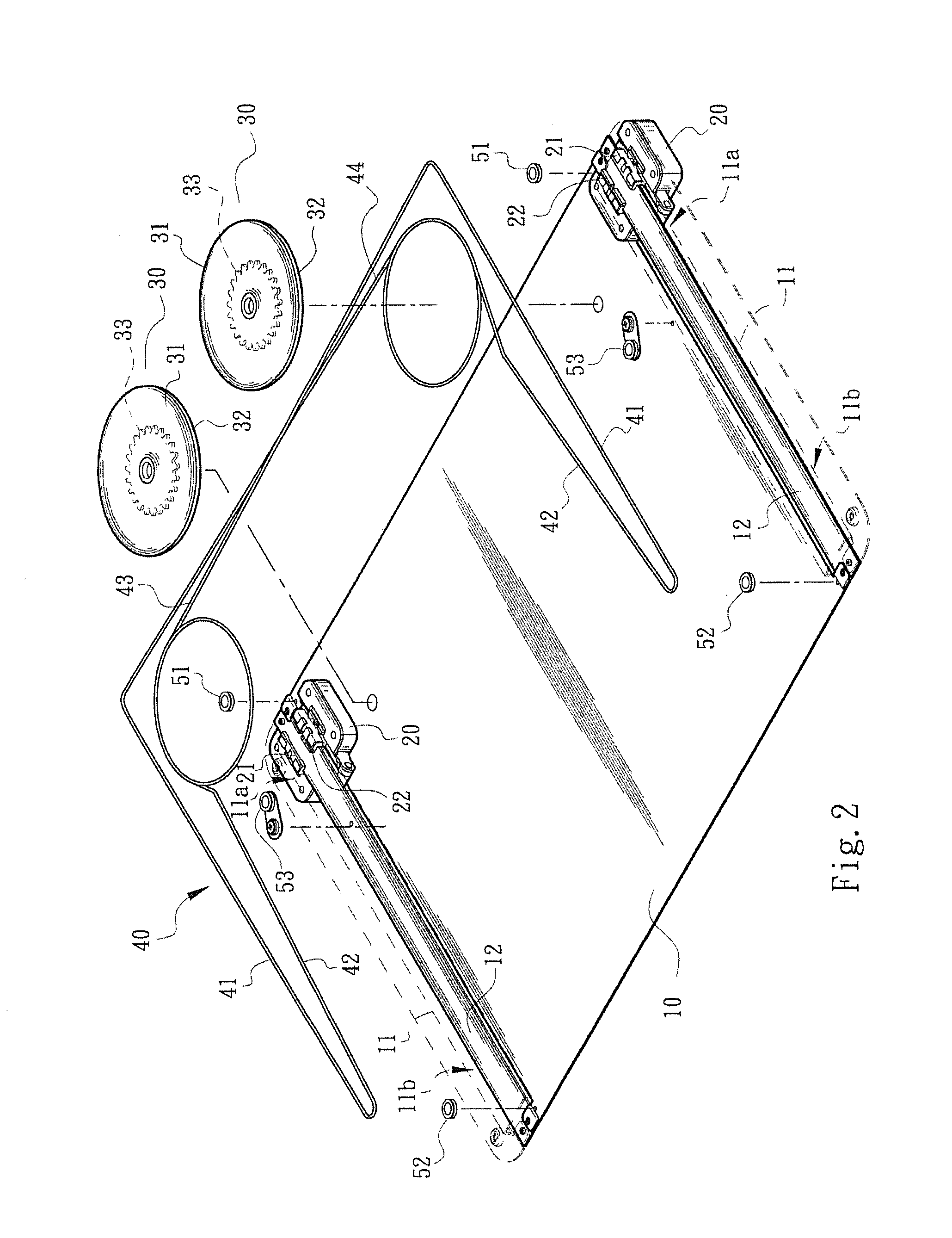
[0020]Referring to FIGS. 1 and 2, an auxiliary device of the invention for a sliding module comprises a substrate 10, two movable or sliding racks 20, two belt wheels 30 and a wire 40. The substrate 10, selected of a plate formed of a type of integral formation, is disposed on a fixed body of an electronic device (not shown in FIGs.). In the adopted embodiment, the substrate 10 comprises two guiding portions 11 represented by imaginary lines of FIGS. 1 and 2. The sliding racks 20, utilized for pivoting the wire 40 and disposed on the guiding portions 11 of the substrate 10, are movable on the guiding portions 11 of the substrate 10. The sliding racks 20 are capable of assembling to a movable body or a sliding unit (not shown in FIGs.) of an electronic device. The belt wheels 30 are rotatably disposed on the substrate 10, and the wire 40 is disposed on the belt wheels 30.
[0021]In FIGS. 1 and 2, the guiding portions 11 of the substrate 10, formed of types of slot chambers, are respectively attached with sliding rails 12, and the sliding racks 20 are respectively installed on the sliding rails 12, so that the sliding racks 20 are movable on the sliding rails 12, or it is summarily that the sliding racks 20 are movable on the guiding portions 11 of the substrate 10. In a preferred embodiment, the guiding portions 11 and the substrate 10 are formed of a type of integral formation or of a type of two individual independent components assembled to each other. Each guiding portion 11 is defined with a first end 11a and a second end 11b.
[0022]In FIG. 2, at least one hand portion 21 is provided on the bottom surface or the lower portion of each sliding rack 20, so that the sliding rack 20 is attached to the sliding rail 12 (or the guiding portion 11) via the hand portion 21 thereof. Each sliding rack 20 further comprises a limit portion 22 formed on the hand portion 21 and utilized to attach or fixedly assemble the wire 40 thereon. In the adopted embodiment, the limit portion 22 is formed of a type of a rabbet to embed or clamp the wire 40.
[0023]In a preferred embodiment, each belt wheel 30 has a periphery or circumferential end surface 31 formed of a type of a recess 32 for winding the wire 40 therein. The belt wheel 30 is further provided with a gear portion 33 utilized to drive a follower wheel or another transmission mechanism and the related content will be described hereinafter.
[0024]Referring to FIGS. 1 and 2, two line segments 41 of the wire 40 are arranged in the guiding portion 11 of the substrate 10 and utilized to pivot to the limit portions 22 of the sliding racks 20, respectively. Further, two sets of positioning wheels 51 and 52 are disposed on regions located in the vicinity of two ends, i.e., the first and second ends 11a and 11b, of the guiding portions 11 of the substrate 10, respectively. The rest of line segments 42, 43 and 44 of the wire 40, outwardly exposed by the guiding portion 11 of the substrate 10, are wound on the positioning wheels 51 and 52 and the belt wheel 30. In the adopted embodiment, the positioning wheels 51 and 52 are selected of rotational or non-rotational type. Two tension pulleys 53 is further provided on the substrate 10 to adjust the tightness of the wire 40 arranged on the positioning wheels 51 and 52 and the belt wheel 30.
[0025]In this embodiment, reference numbers 41, 42 and 43/44 stand for line segments of the wire 40 located in the guiding portions 11 of the substrate 10, between the positioning wheels 52 and the belt wheels 30, between the positioning wheels 51 and the belt wheels 30, respectively.
[0026]Referring to FIG. 3, the assembly and movement condition of the guiding portions 11, the sliding racks 20, the belt wheels 30 and the wire 40 are represented. In FIG. 3, it presumes that the sliding module represented by real line is in a closed position (i.e., the sliding rack 20 is located at the first end 11a of the guiding portion 11) to be defined as a first position, and the sliding module represented by imaginary line is in an open position (i.e., the sliding rack 20 is located at the first end 11b of the guiding portion 11) to be defined as a second position.
[0027]When each the sliding rack 20 driven by the sliding module is moved from the first end 11a (or the first position) to the second end 11b (or the second position) of the guiding portion 11, the sliding racks 20 drive the line segments 41 of the wire 40 to move toward the bottom of this figure, so that the line segments 42 of the wire 40 are moved toward the top of this figure to rotate the belt wheels 30. In FIG. 3, the rotation directions of the belt wheels 30 are indicated by arrows marked thereon, respectively. Further, the rotations of the belt wheels 30 drive the line segments 43 and 44 of the wire 40 to move toward the positioning wheels 51 to enter the guiding portions 11 of the substrate 10, respectively. It is therefore that, the movement of the wire 40 is a circulatory movement, and the sliding module is turned to the open status until the sliding racks 20 are moved to the second ends 11b of the guiding portions 11 of the substrate 10 (i.e., the position represented by imaginary line in FIG. 3).
[0028]It is understood that when each sliding rack 20 is reversed from the second end 11b (or the second position) to the first end 11a (or the first position) of the guiding portion 11, the sliding racks 20 drive the line segments 41 of the wire 40 to move toward the top of this figure, so that the line segments 42 of the wire 40 are moved toward the bottom of this figure to rotate the belt wheels 30, and the rotation of the belt wheels 30 drive the line segments 43 and 44 of the wire 40 to move from the positioning wheels 51 toward the belt wheels 30, respectively. The sliding module is turned to the closed status until the sliding racks 20 are moved to the first ends 11a of the guiding portions 11 (i.e., the position represented by imaginary line in FIG. 3), respectively.
[0029]In an applicable embodiment, the belt wheels 30 can be utilized to drive transmission mechanisms, represented by imaginary line in FIG. 3, to perform another motion or function. For example, each belt wheel 30 is utilized to drive a follower wheel 60 which drives a rotating wheel 70 and a toggle mechanism 80. When the rotating wheels 70 are rotated, a gate 90 is simultaneously driven by the rotating wheels 70 to generate linear displacement.
[0030]Specifically, each toggle mechanism 80 comprises a first arm 81 pivoted to the rotating wheel 70, a second arm 82 pivoted to the first arm 81, and an elastic member 83 disposed between the first arm 81 and the second arm 82. Therefore, the wire 40 drives the belt wheels 30, the follower wheels 60 and the rotating wheels 70 for rotation movement when a sliding cover module drives the sliding racks 20 for reciprocal movement, so that the elastic members 83 of the toggle mechanisms 80 store energy therein, or release energy therefrom to generate acting forces to assist with the rotation of the rotating wheels 70. That is, the design of the transmission mechanisms such as the rotating wheels 70, the toggle mechanisms 80 and the gate 90 are capable of providing the acting forces to assist with the movements of the sliding cover module, the belt wheels 30 and the sliding racks 20.
[0031]Typically speaking, with the co-operative movement of the sliding cover module, the auxiliary device of the invention for the sliding module provides the following particular considerations and advantages, compared to conventional skills.
[0032]By cooperating the belt wheels 30 and the wire 40 with the sliding racks 20 disposed on the guiding portions 11 (or the sliding rails 12), the unsmooth operation of conventional skills, or shakiness or swing caused by an user applying a single side-pushing force to operate the sliding cover module or mechanism can be minimized.
[0033]The invention provides a reliable arrangement design, totally different from conventional skills, for the structural pattern of the auxiliary device to assist in enhancing the motion stability and smoothness of the sliding module. In particular, the auxiliary device of the invention especially suitable for a movable body (or the sliding cover components) of an electronic device with heavy weight and large size.
[0034]To sum up, the invention provides an effective auxiliary device suitable for the sliding module and a particular space configuration much different from that in the conventional skills, and therefore the advantages and improvements of the invention certainly surpass the conventional skills.
[0035]While the invention has been described by way of example and in terms of the preferred embodiments, it is to be understood that the invention is not limited to the disclosed embodiments. To the contrary, it is intended to cover various modifications and similar arrangements (as would be apparent to those skilled in the art). Therefore, the scope of the appended claims should be accorded the broadest interpretation so as to encompass all such modifications and similar arrangements.

PUM

no PUM

Description & Claims & Application Information

We can also present the details of the Description, Claims and Application information to help users get a comprehensive understanding of the technical details of the patent, such as background art, summary of invention, brief description of drawings, description of embodiments, and other original content. On the other hand, users can also determine the specific scope of protection of the technology through the list of claims; as well as understand the changes in the life cycle of the technology with the presentation of the patent timeline. Login to view more.

Similar technology patents

Method and Apparatus Performing Automatic Mapping for A Multi-Processor System

InactiveUS20090006072A1minimize operation
Owner:MASSACHUSETTS INST OF TECH

Quick disk player configuration to send content to TV

InactiveUS20120093478A1minimize operation
Owner:SONY CORP

Apparatus and method for inspecting liquid crystal display

ActiveUS20070046317A1reduce maintenance costminimize operation
Owner:LG DISPLAY CO LTD

Method for detecting icing and de-icing

ActiveUS20200018293A1limit riskminimize operation
Owner:ELECTRICITE DE FRANCE +2

Classification and recommendation of technical efficacy words

  • minimize operation

Method and Apparatus Performing Automatic Mapping for A Multi-Processor System

InactiveUS20090006072A1minimize operation
Owner:MASSACHUSETTS INST OF TECH

Apparatus and method for inspecting liquid crystal display

ActiveUS20070046317A1reduce maintenance costminimize operation
Owner:LG DISPLAY CO LTD

Quick disk player configuration to send content to TV

InactiveUS20120093478A1minimize operation
Owner:SONY CORP

Method for detecting icing and de-icing

ActiveUS20200018293A1limit riskminimize operation
Owner:ELECTRICITE DE FRANCE +2
Why Eureka
Try Eureka