Automatic resetting torque limiter capable of high speed continuous operations in released mode

a technology of automatic resetting and torque limiter, which is applied in the direction of couplings, slip couplings, couplings, etc., can solve the problems of reducing the service life of the torque limiter, failure or change of the set and reset torque levels, and the capacity of the clutch to fade, so as to achieve not excessively noisy

Active Publication Date: 2014-04-15
BRUNEL GMBH
View PDF3 Cites 0 Cited by
  • Summary
  • Abstract
  • Description
  • Claims
  • Application Information

AI Technical Summary

Benefits of technology

[0016]The above recited objects and other objects which will be understood upon a reading of the following specification and claims are achieved by providing a particular engagement surface curved shape which does not create large dynamic loads or stresses in the components which exceed the elastic limit of the elements even when operated at high speeds of 1800 rpm or greater such as to minimize shocks and resultant wear and noise during operation.

Problems solved by technology

The disadvantage of this arrangement is that repeated heating of the torque limiter friction linings (as heat is generated by the slipping) causes the clutch capacity to fade, as the higher lining temperatures reduces the coefficient of friction, until the torque limiter slips continuously and destroys itself.
The disadvantage of this device is the sudden changes in the acceleration of the connected components, which produces stresses in the material which exceeds the elastic limits of the components when running, disengaged, or when reengaging, which in turn produces deformations which greatly reduce the torque limiter service life.
This could cause deformation of the mating torque limiter components, leading to failure or to changes in the set and reset torque levels due to deformations of the follower elements or engagement surfaces.
These applications create severe demands in cases where access to the torque limiters is very difficult or impossible as when the machine is located in tight spaces such as in tunneling and mining operations.
In these applications, a torque limiter will likely be operated in the disengaged mode for extended time periods, and complete failures or significant degrading of performance would be very undesirable and costly.
A satisfactory torque limiter for such high speed limited access applications has not yet been developed.
In the field of cams design in a machine where there is a particular designed for output motion there has long been recognition that simply smoothly curving these surfaces is not sufficient to avoid shocks and early failures.
However, in the field of automatic resetting torque limiters, it has not heretofore been recognized that simply smoothly curving the engagement surfaces which are engaged by drive elements is not sufficient to eliminate noise and impact wear of the engagement surfaces and elements when continuously operating in the released condition at high speeds, i.e. around 1800 rpm or higher.
In fact, despite a long felt need for such a torque limiter, no automatically reset torque limiter has been produced which can operate successfully under those conditions.

Method used


Image

  • Automatic resetting torque limiter capable of high speed continuous operations in released mode
  • Automatic resetting torque limiter capable of high speed continuous operations in released mode
  • Automatic resetting torque limiter capable of high speed continuous operations in released mode

Examples


Embodiment Construction

[0028]In the following detailed description, certain specific terminology will be employed for the sake of clarity and a particular embodiment described in accordance with the requirements of 35 USC 112, but it is to be understood that the same is not intended to be limiting and should not be so construed inasmuch as the invention is capable of taking many forms and variations within the scope of the appended claims.

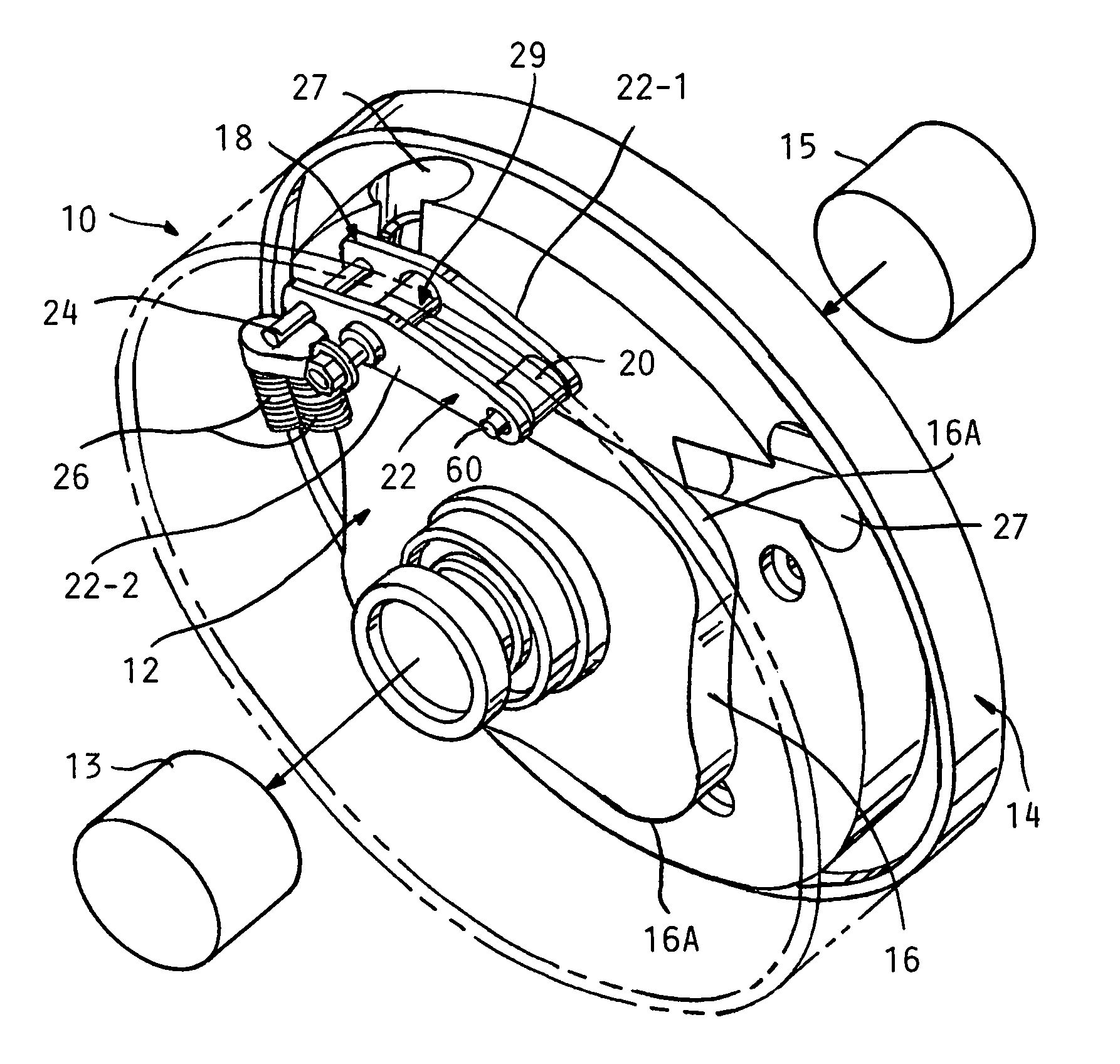
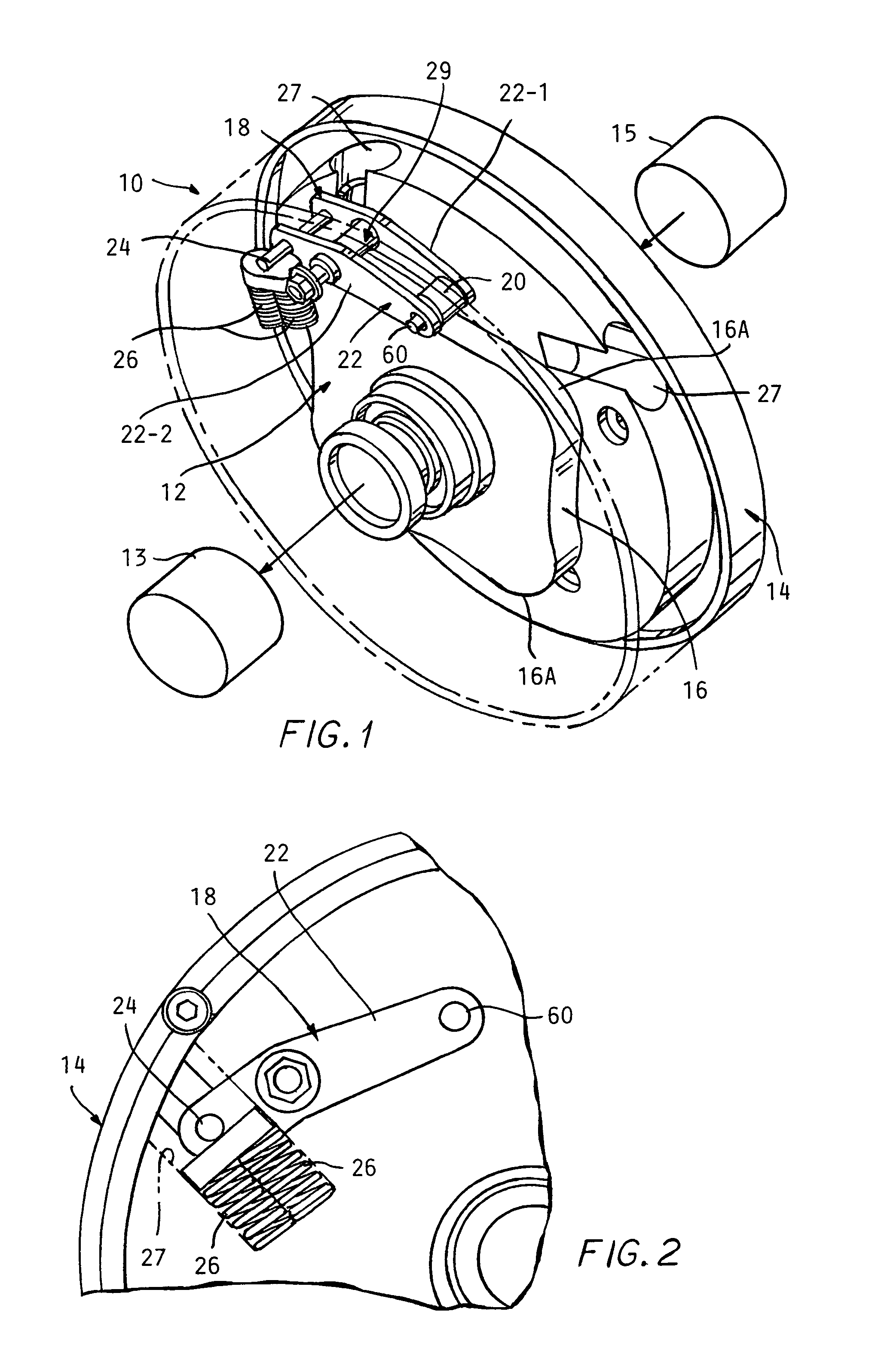
[0029]A torque limiter 10 which is automatically resettable is shown in FIG. 1.

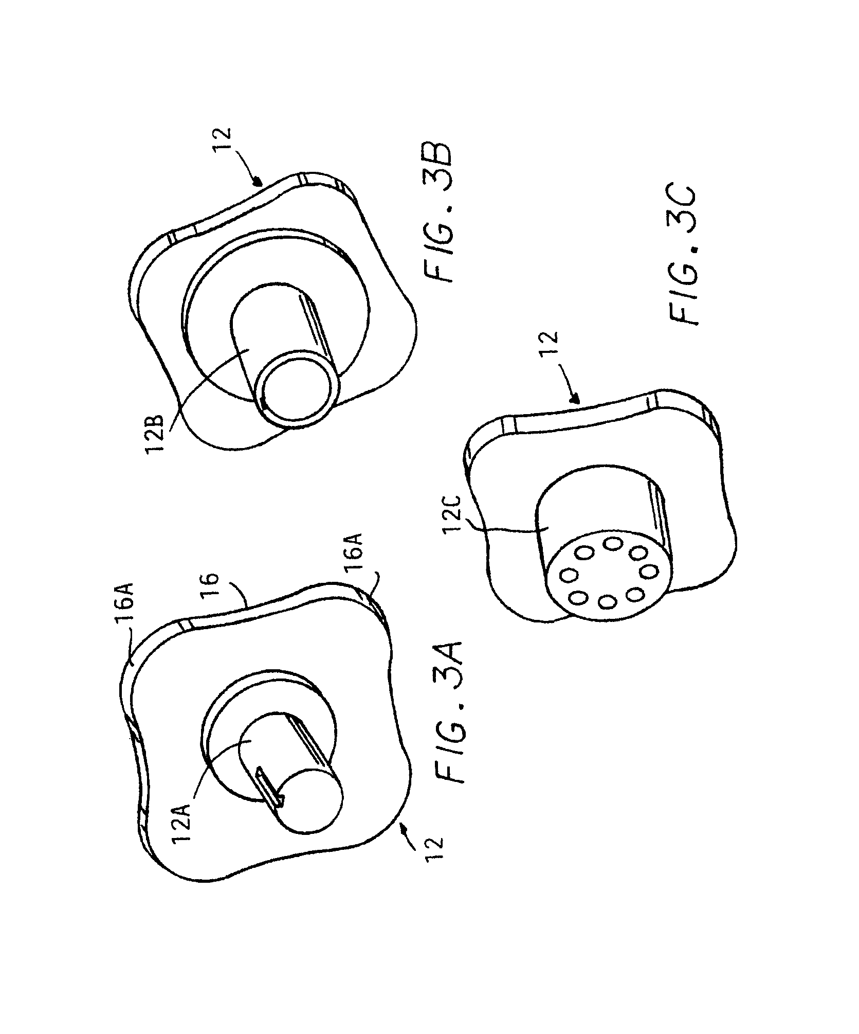
[0030]The automatically resetting torque limiter 10 includes two relatively rotatable rotary members 12, 14. One of the members shown as 14 in FIG. 1, is drivingly connected to a source of power 15 such as an electric motor, the other of the members shown as 12 in FIG. 1, is drivingly connected to driven machinery 13. One member 12 is formed with an engagement surface 16, which extends circumferentially about the axis of rotation of the member 12. The engagement surface 16 in this embodiment u...


PUM


Abstract

A resettable torque limiter for installation between two rotary members, which can smoothly disengage upon application of predetermined torque acting between the members and smoothly reset upon decline of applied torque below the predetermined level. An undulating engagement surface formed on one member according to a function preferably an eighth power polynomial is engaged by a plurality of engagement elements on the other member which smoothly ride over lobes formed on the engagement surface when the torque limit is exceeded without causing any discontinuities in acceleration or jerk when the driving connection between the rotary members is interrupted until the applied torque declines below the preset limit.

Description

CROSS REFERENCE TO RELATED APPLICATIONS[0001]This application is a continuation in part of U.S. patent application Ser. No. 12 / 481,701 filed on Jun. 20, 2009 now abandoned, which claims the benefit of U.S. provisional application No. 61 / 060,288 filed on Jun. 10, 2008, the corresponding published application no. 2009-0305794-A1 is incorporated herein by reference.BACKGROUND OF THE INVENTION[0002]This invention concerns automatically resetting torque limiting clutches, commonly referred to as limiters and more particularly automatically resetting torque limiters which can disconnect drive on overload.[0003]Torque limiters are designed to release a driving connection when an excessive load is experienced. Such limiters are typically used in the context of a drive for various types of machinery subject to jams and other overloads in order to not damage the driving motor or the machinery. In most instances, the release of the torque limiter is noticed soon after it occurs since the machi...

Claims


Application Information

Patent Timeline
Patent Type & Authority Patents(United States)
IPC IPC(8): F16D7/04
CPCF16D7/048F16D43/2028F16D7/021
Inventor LONG, JR., THOMAS F.RUDOLPH, MARK WAYNE
Owner BRUNEL GMBH
Why Eureka
Try Eureka