Image forming apparatus and image forming method

a technology of image forming apparatus and forming method, which is applied in the direction of electrographic process apparatus, instruments, optics, etc., can solve the problems of increasing thermal energy consumption, requiring excessively long time to increase the temperature of pressure roller, and unsatisfactory tight curl of medium or low-temperature offset, etc., to achieve more stable fixing process, reduce undesirable influence on user, and reduce yield

Active Publication Date: 2012-12-27
KONICA MINOLTA INC
View PDF2 Cites 4 Cited by
  • Summary
  • Abstract
  • Description
  • Claims
  • Application Information

AI Technical Summary

Benefits of technology

[0020]The present invention was made to solve the above-described problems, and its object is to provide image forming apparatus and image forming method enabling execution of more stable fixing process while reducing undesirable influence to the user such as lower yield.

Problems solved by technology

If images are formed continuously on a plurality of media (when sheets are fed continuously), the temperature of pressure roller decreases significantly, resulting in undesirably tight curl of the medium or a low-temperature offset.
Specifically, the method of making longer the warm-up period immediately after activation may require excessively long time to increase the temperature of pressure roller unless the pressure roller can be heated with high efficiency.
The method of increasing set values related to temperature control increases thermal energy consumption.
Further, the method of reducing yield immediately after activation leads to waste of time of the user.

Method used


Image

  • Image forming apparatus and image forming method
  • Image forming apparatus and image forming method
  • Image forming apparatus and image forming method

Examples


Embodiment Construction

[0045]An embodiment of the present invention will be described in detail with reference to the figures. The same or corresponding portions in the figures are denoted by the same reference characters, and description thereof will not be repeated.

[A. Outline]

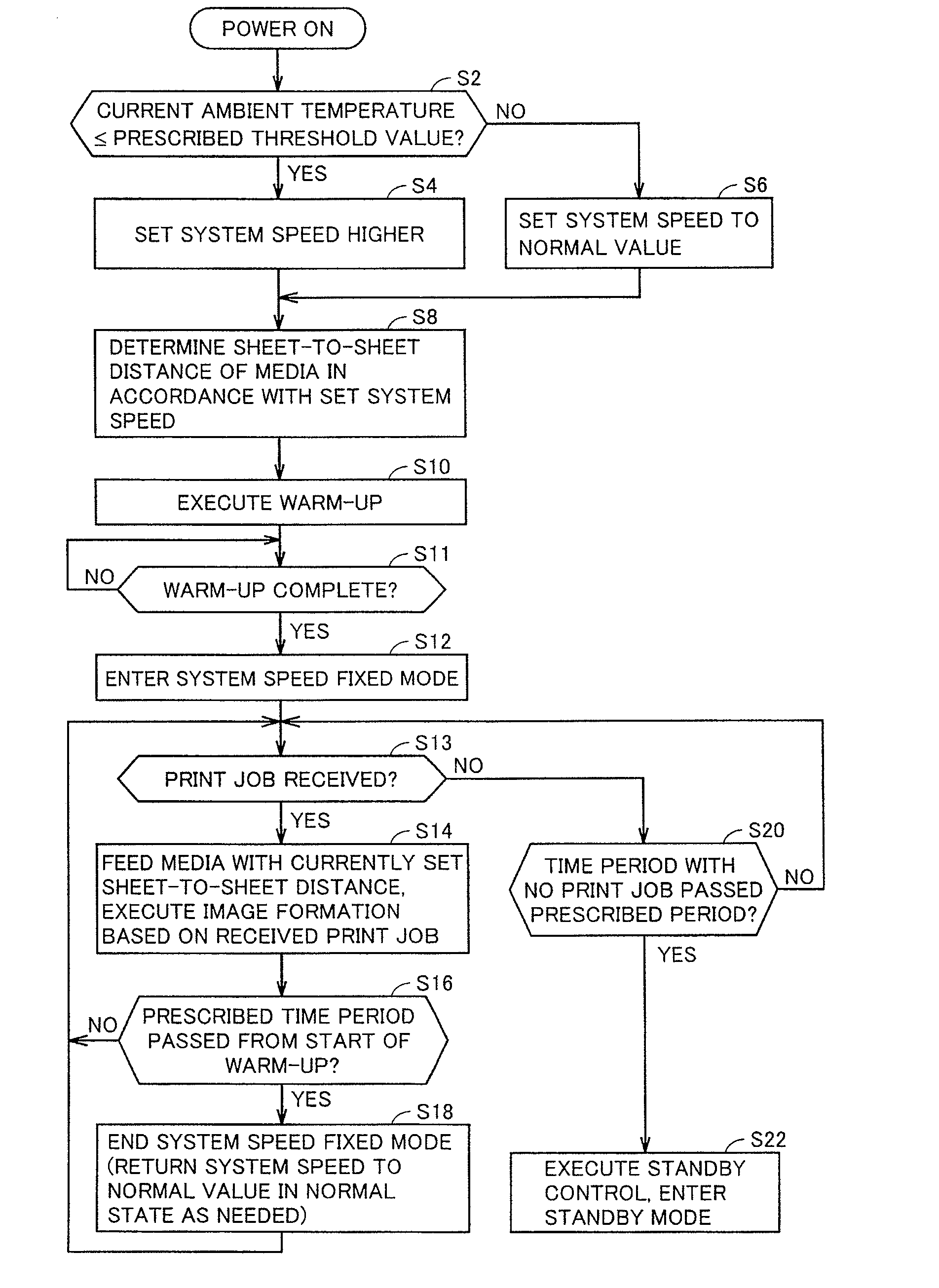
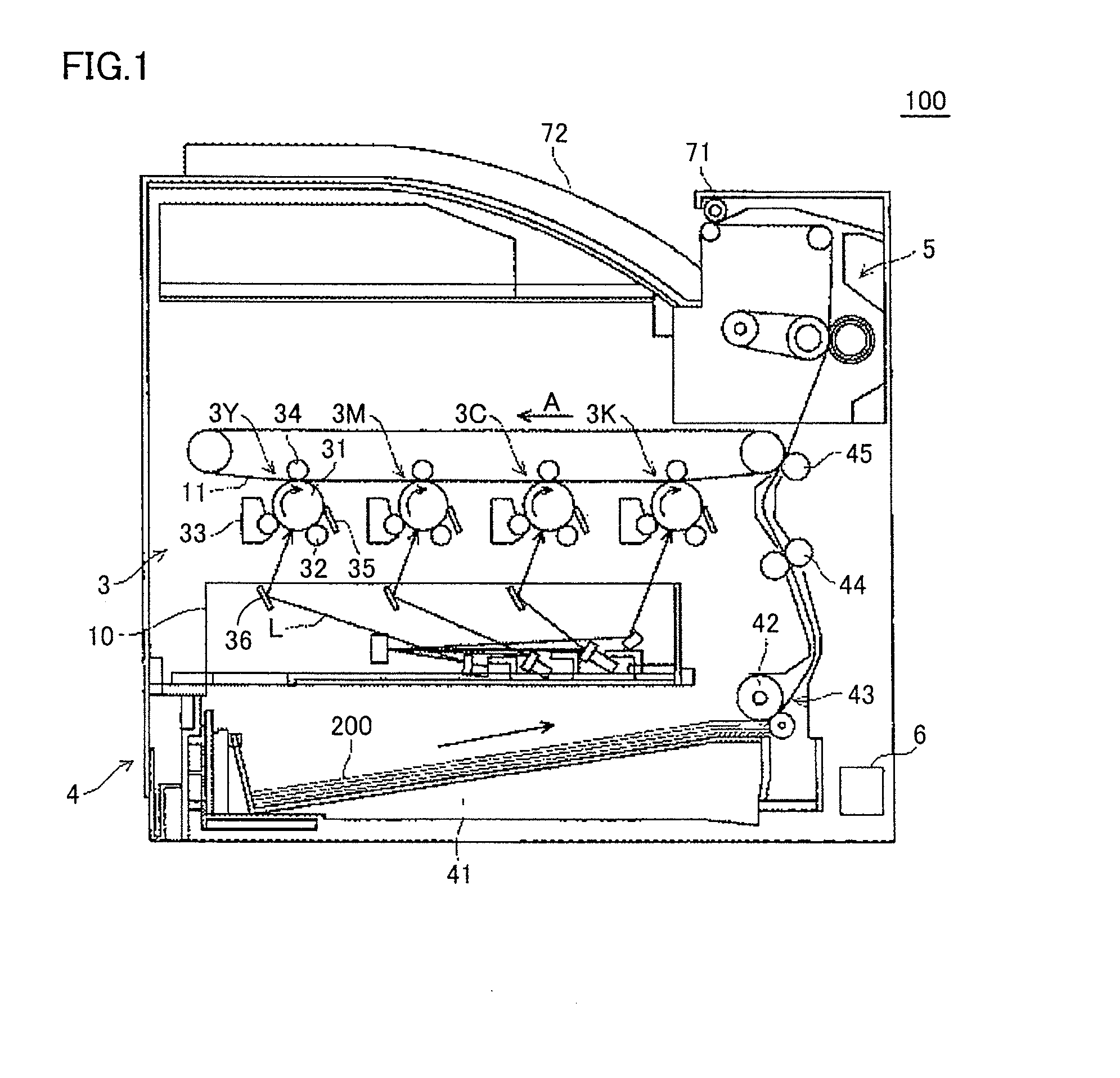
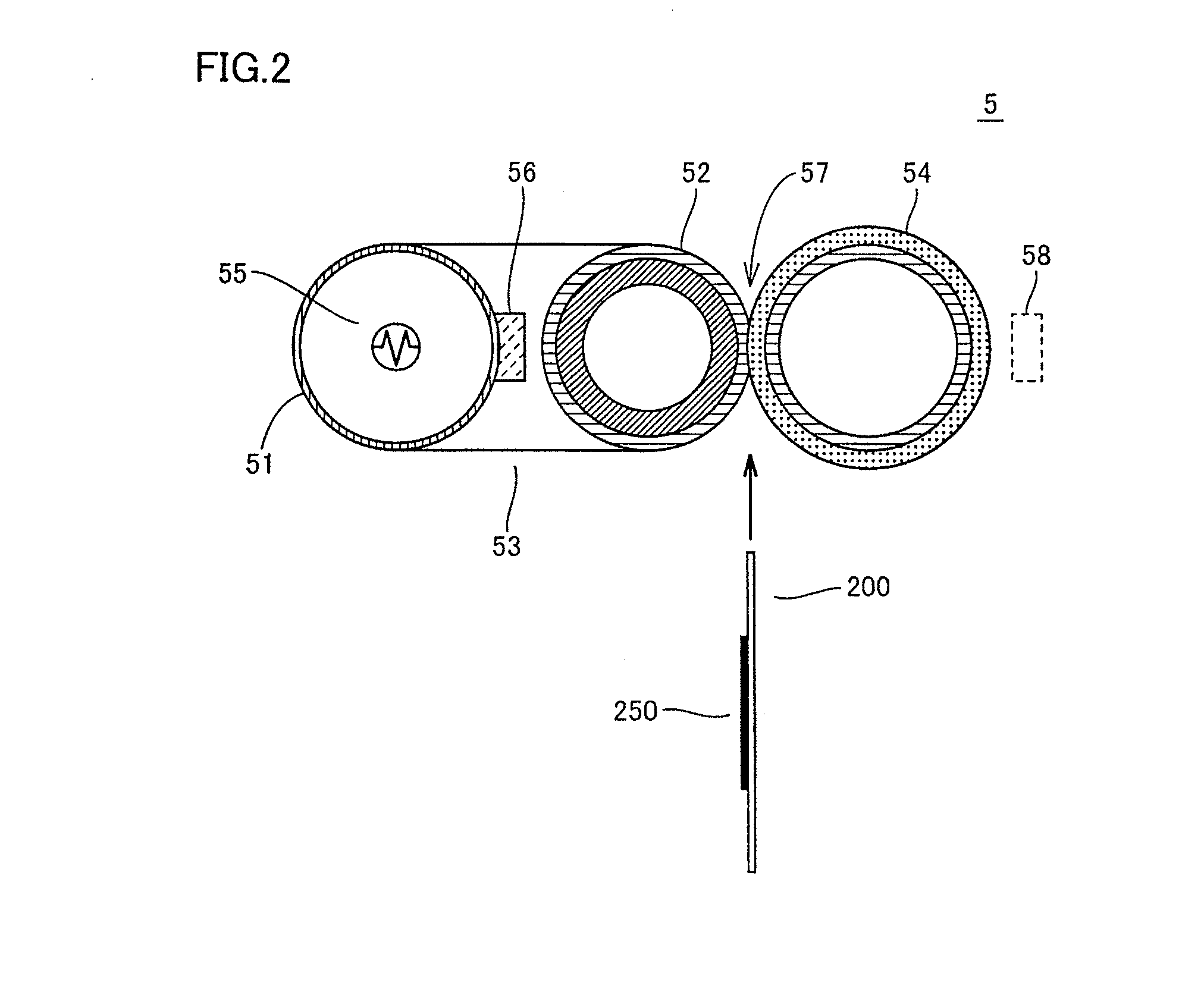
[0046]The fixing device in accordance with the present embodiment includes: a heating roller having a heater as a heat source, supported rotatably at opposite ends; an endless fixing belt wound around a rotatably supported fixing roller; and a rotationally driven pressure roller, in contact with an outer circumference of the fixing belt, applying load to the fixing roller to form a nip portion. The fixing roller is rotatably attached to a side plate, and the belt is spanned with tension by means of a compression spring provided between the side plate and a heating roller supporting member. Thus, when the pressure roller is driven, the fixing belt and the fixing roller follow.

[0047]Typically, before executing warm-up control after ...


PUM


Abstract

An image forming apparatus includes an image forming section, a heat source, a fixing rotating body, a pressurizing rotating body, a feeding section for feeding a medium, a temperature adjusting section for controlling an amount of heat generated by the heat source, and a control section. The control section switches between a first mode in which the fixing rotating body and the pressurizing rotating body rotate at a first circumferential speed and the medium is fed to the image forming section at a first distance interval, and a second mode in which the fixing rotating body and the pressurizing rotating body rotate at a second circumferential speed higher than the first circumferential speed and the medium is fed to the image forming section at a second distance interval longer than the first distance interval.

Description

[0001]This application is based on Japanese Patent Application No. 2011-138039 filed with the Japan Patent Office on Jun. 22, 2011, the entire content of which is hereby incorporated by reference.BACKGROUND OF THE INVENTION[0002]1. Field of the Invention[0003]The present invention relates to an image forming apparatus mounting a fixing device used for an electrophotographic image forming process, as well as to an image forming method.[0004]2. Description of the Related Art[0005]In a general electrophotographic image forming process, a toner image formed on a medium (e.g. sheet) is heated and pressed, so that the image is fixed. A fixing device for fixing the toner image in this manner typically has a heating roller as a heating rotating body and a pressure roller as a pressurizing rotating body. The heating roller is heated by a heat source such as a heater.[0006]In such a fixing device, in order to have a not-yet-fixed toner image fixed on the medium, surface temperature of the hea...

Claims


Application Information

Patent Timeline
Patent Type & Authority Applications(United States)
IPC IPC(8): G03G15/20
CPCG03G15/2078G03G15/657G03G2215/00599G03G15/2039G03G2215/00949G03G2215/0132G03G2215/00945
Inventor MATSUO, RYOHEIAOKI, TOSHIYA
Owner KONICA MINOLTA INC
Why Eureka
Try Eureka