Anti-skid stud for insertion into the tread of a vehicle tire and pneumatic tire comprising such Anti-skid studs
- Summary
- Abstract
- Description
- Claims
- Application Information
AI Technical Summary
Benefits of technology
Problems solved by technology
Method used
Image

Examples
first embodiment
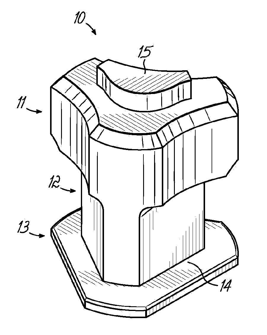
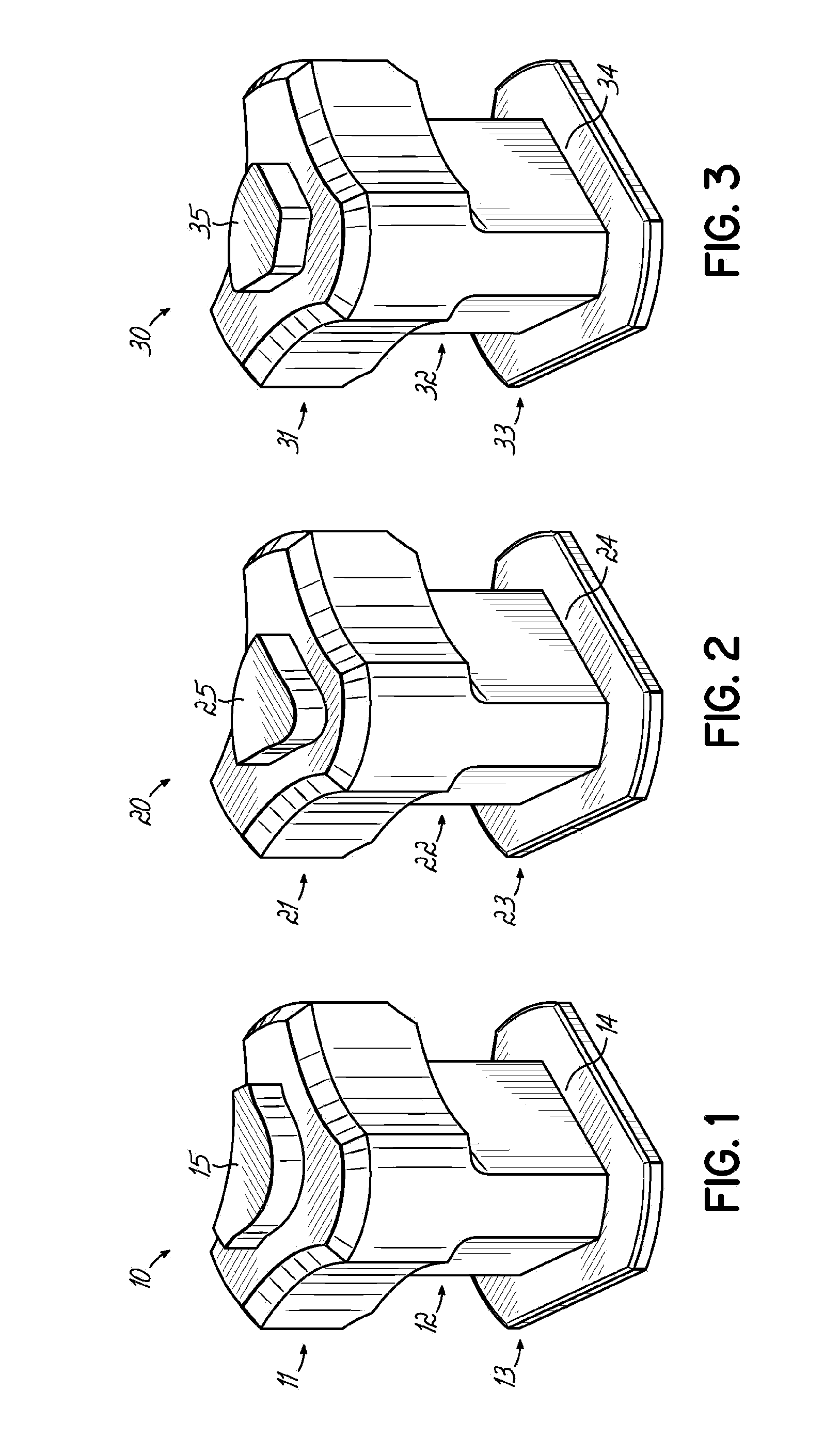
[0109]FIG. 1 shows in the invention an anti-skid stud 10 consisting of a support body part 14 and a pin body part 15. The support body part comprises a head portion 11, a middle portion 12 and a bottom portion 13.
[0110]The support body part 14 comprises a receptacle with the pin body part 15 inserted into the receptacle and secured to the support body part 14 via press fit. The support body part 14 may be made from aluminum or steel. The pin body part 15 may be made from a commonly used hard ceramic material or hard metal material and extends axially beyond the upper surface of the head portion 11. As shown in FIG. 1, the head portion 11 has a larger size or diameter than the middle portion 12. The bottom portion 13 has also a larger size or diameter than the middle portion 12. The different shape of bottom portion 13, middle portion 12 and head portion 11 makes these parts of the anti-skid stud 10 distinguishable as separate sections of the anti-skid stud 10. The size of the bottom...
second embodiment
[0119]FIG. 2 shows in the invention an anti-skid stud 20 consisting of a support body part 24 and a pin body part 25. The support body part comprises a head portion 21, a middle portion 22 and a bottom portion 23.
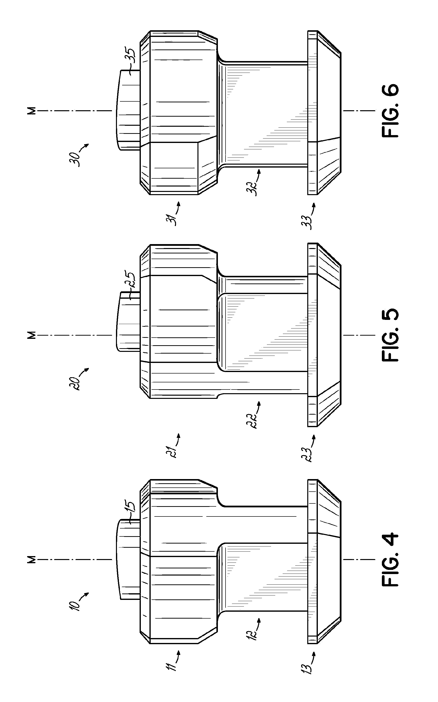
[0120]FIG. 5 shows a side view of FIG. 2. FIG. 8 shows a top view of FIG. 2. FIG. 11 shows a perspective view from the bottom side of FIG. 2. FIG. 14 is a bottom view of FIG. 2 showing the underside 50 of the anti-skid stud 20 comprising a recess 51 having the shape of a hemisphere.
[0121]Besides the shape of the pin body 25, the shape, dimensions and materials of the anti-skid stud 20 may be the same as the anti-skid body 10. The pin body 25 has substantially the shape of a sector 44 of a circle with rounded edges with two concave shaped sides of the same length and shape, one longer convex shaped side and one opposite shorter convex side (which may also be called a rounded edge).
third embodiment
[0122]FIG. 3 shows in the invention an anti-skid stud 30 consisting of a support body part 34 and a pin body part 35. The support body part comprises a head portion 31, a middle portion 32 and a bottom portion 33.
[0123]FIG. 6 shows a side view of FIG. 3. FIG. 9 shows a top view of FIG. 3. FIG. 12 is a perspective view from the bottom side of FIG. 3. FIG. 15 is a bottom view of FIG. 3 showing the underside 50 of the anti-skid stud 20 comprising a recess 51 having the shape of an hemisphere.
[0124]Besides the shape of the pin body 35, the shape, dimensions and materials of the anti-skid stud 30 again may be the same as the anti-skid body 10. The pin body 35 has substantially the shape of an annulus 45 with rounded edges with one straight line, two concave sides of the same length and shape and one convex side opposite the straight line. The shape of the pin body 35 may also have substantially the shape of a trapezium with rounded edges or having the shape of a tetragon without slightly...
PUM
 Abstract
Description
Claims
Application Information
 - Generate Ideas
- Intellectual Property
- Life Sciences
- Materials
- Tech Scout
- Unparalleled Data Quality
- Higher Quality Content
- 60% Fewer Hallucinations
Browse by: Latest US Patents, China's latest patents, Technical Efficacy Thesaurus, Application Domain, Technology Topic, Popular Technical Reports.
© 2025 PatSnap. All rights reserved.Legal|Privacy policy|Modern Slavery Act Transparency Statement|Sitemap|About US| Contact US: help@patsnap.com