Occupant protection device

Active Publication Date: 2013-01-03
SUBARU CORP
View PDF7 Cites 60 Cited by
  • Summary
  • Abstract
  • Description
  • Claims
  • Application Information

AI Technical Summary

Benefits of technology

[0012]Accordingly, it is an object of the present invention to provide an occupant protection device that makes the impact values in different

Problems solved by technology

In particular, if a seat belt lies across the chest of an occupant, the seat belt might compress the chest of the occupant upon a vehicle being subjected to an impac

Method used


Image

  • Occupant protection device
  • Occupant protection device
  • Occupant protection device

Examples


embodiment 1

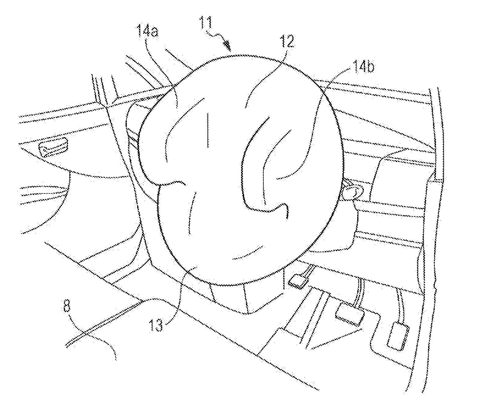
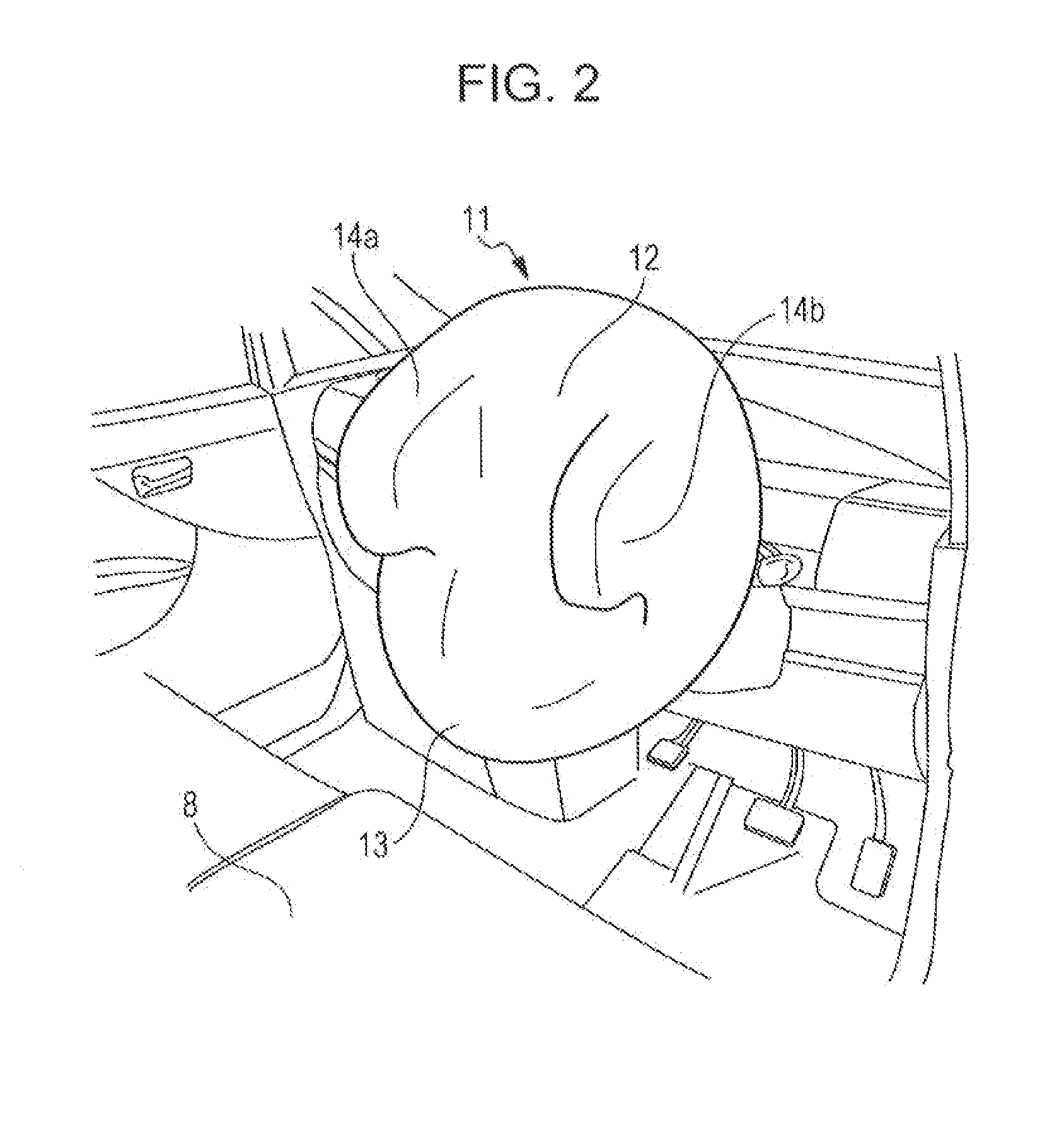
[0036]An airbag device (occupant protection device) 10 of Embodiment 1 of the present invention is stored in a center pad 7 of a steering wheel 3.

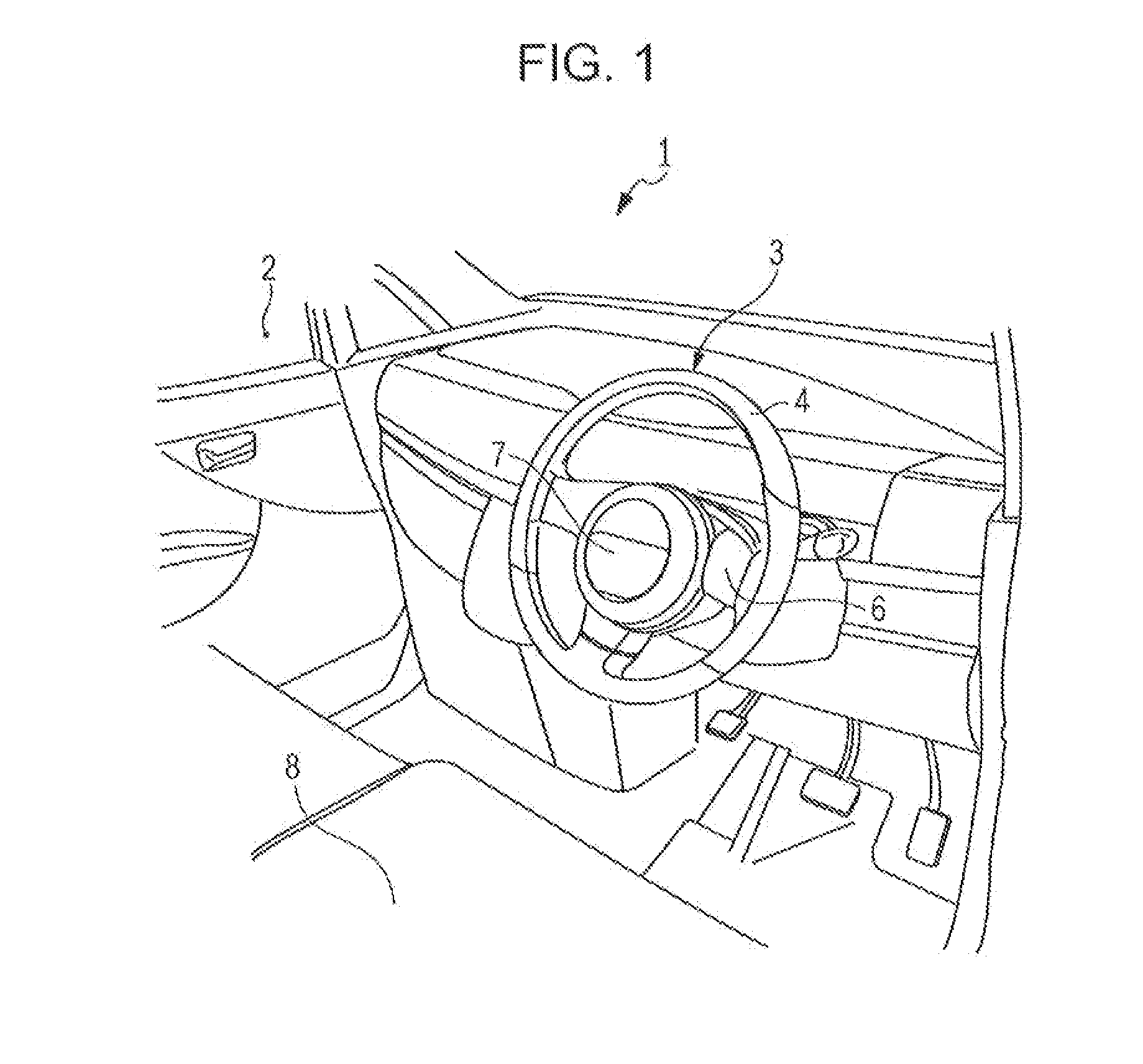
[0037]First, a description is given of the steering wheel 3 of a vehicle 1 to which the airbag device 10 of Embodiment 1 of the present invention is applied with reference to FIG. 1. FIG. 1 is a schematic view showing a cabin 2 of the vehicle 1 to which the airbag device 10 of Embodiment 1 of the present invention is applied. More specifically, FIG. 1 is a perspective view showing the cabin 2 as viewed from the rear toward the front of the vehicle 1.

[0038]As illustrated in FIG. 1, the steering wheel 3 of this embodiment includes a ring-shaped rim 4 forming an outer frame of the steering wheel 3, spokes 6 connecting the rim 4 and a steering shaft 5, and a center pad 7 provided separately from the steering shaft 5 and supported so as to have an independent non-rotating structure.

[0039]That is, the center pad 7 of this embodiment is configure...

modified example 1 of embodiment 1

[0072]Next, a description is given of Modified Example 1 of Embodiment 1 with reference to FIGS. 6 and 7. First, a description, is given of an airbag 21 of an airbag device 20 of this modified example with reference to FIG. 6. FIG. 6 is a schematic view showing a cabin 2 of a vehicle 1 to which the airbag device 20 of Modified Example 1 of Embodiment 1 of the present invention is applied. More specifically, FIG. 6 is a perspective view showing the airbag 21 of the airbag device 20 in an inflated and expanded state.

[0073]This airbag device 20 is the same as that of the above Embodiment 1 except for the shape of the airbag 21 in the inflated and expanded state. Accordingly, the elements corresponding to those of the above Embodiment 1 are referred to by the same reference numerals, and a description thereof is omitted.

[0074]As illustrated in FIG. 6, the airbag 21 of the airbag device. 20 of this modified example includes a first chamber (head protection chamber) 22 and a second chambe...

modified example 2 of embodiment 1

[0084]Next, a description is given of Modified Example 2 of Embodiment 1 with reference to FIGS. 8 and 9. First, description is given of an airbag 31 of this modified example with reference to FIG. 8. FIG. 8 is a schematic view showing a cabin 2 of a vehicle 1 to which an airbag device 30 of Modified Example 2 of Embodiment 1 of the present invention is applied. More specifically, FIG. 8 is a perspective view showing the airbag 31 of the airbag device 30 in an inflated and expanded state.

[0085]This airbag device 30 is the same as that of the above Embodiment 1 except for the shape of the airbag 31 in the inflated and expanded state. Accordingly, the elements corresponding to those of the above Embodiment 1 are referred to by the same reference numerals, and a description thereof is omitted.

[0086]As illustrated in FIG. 8, the airbag 31 of the airbag device 30 of this modified example includes a first chamber (head protection chamber) 32 and a second chamber (chest protection chamber)...


PUM


Abstract

There is provided an occupant protection device. An airbag device includes an airbag that is stored in a center pad of a steering wheel of a vehicle and is expandable toward an occupant side upon a collision of the vehicle. The center pad is disposed to have a non-rotating structure independent from the steering wheel. The airbag includes a first extension portion and a second extension portion which are disposed at opposing edges of the airbag in a width direction of the vehicle and are expandable to extend toward a rear side of the vehicle.

Description

CROSS REFERENCE TO RELATED APPLICATIONS[0001]The present application claims priority from Japanese Patent Application No. 2011-146837 filed on Jun. 30, 2011, the entire contents of which are hereby incorporated by reference.BACKGROUND OF THE INVENTION[0002]1. Field of the Invention[0003]The present invention generally relates to occupant protection devices, and particularly relates to an occupant protection device in which an airbag is stored in a center pad of a steering wheel.[0004]2. Description of the Related Art[0005]There is known an occupant protection device in which an airbag is stored in a folded state in a center pad of a steering wheel and the airbag expands from the center pad toward an occupant in response to an impact due to a collision of a vehicle so as to protect the occupant from the impact.[0006]The center pad of the steering wheel usually rotates together with the steering wheel in accordance with driving operations performed by an occupant. Therefore, the airba...

Claims


Application Information

Patent Timeline
IPC IPC(8): B60R21/203
CPCB60R21/233B60R21/203B60R21/231B60R2021/23316B60R2021/23161B60R2021/23308B60R21/23138
Inventor NAGASAWA, ISAMUBABA, NORIYOSHINAKASE, TETSUYA
Owner SUBARU CORP
Why Eureka
Try Eureka