System and Method fo Dental Implant and Interface to Abutment For Restoration

a technology of dental implants and abutments, applied in dental implants, dental surgery, medical science, etc., can solve the problems of bacteria penetration and subsequent crestal bone loss, interface virtually no stability, and complicated late scenario

Active Publication Date: 2013-01-03
BIOMET 3I LLC
View PDF5 Cites 36 Cited by
  • Summary
  • Abstract
  • Description
  • Claims
  • Application Information

AI Technical Summary

Problems solved by technology

This latter scenario can be more complicated due to the added connection between the implant and the abutment.
Unfortunately, such an interface has virtually no stability until the screw is introduced and fully seated between the abutment and the implant.
While this system has advantages over the external hex implant, the disadvantage (which applies to the external hex as well) is that it is prone to leak at the implant-abutment interface (seating surface) due to “lifting” of the abutment under load that may create an intermittent gap resulting in bacteria penetration and subsequent crestal bone loss.
However, such designs suffer from vertical location variability.
The currently marketed vertical connection implant systems are susceptible to significant vertical location variability, and subsequent customer dissatisfaction.
Known vertical implant systems therefore still allow the lateral movement of the abutment in relation to the implant thus causing the possibility of misalignment.
The increase in seals in a contemplated system may result in adhesion between the implant and the abutment.

Method used


Image

  • System and Method fo Dental Implant and Interface to Abutment For Restoration
  • System and Method fo Dental Implant and Interface to Abutment For Restoration
  • System and Method fo Dental Implant and Interface to Abutment For Restoration

Examples


Embodiment Construction

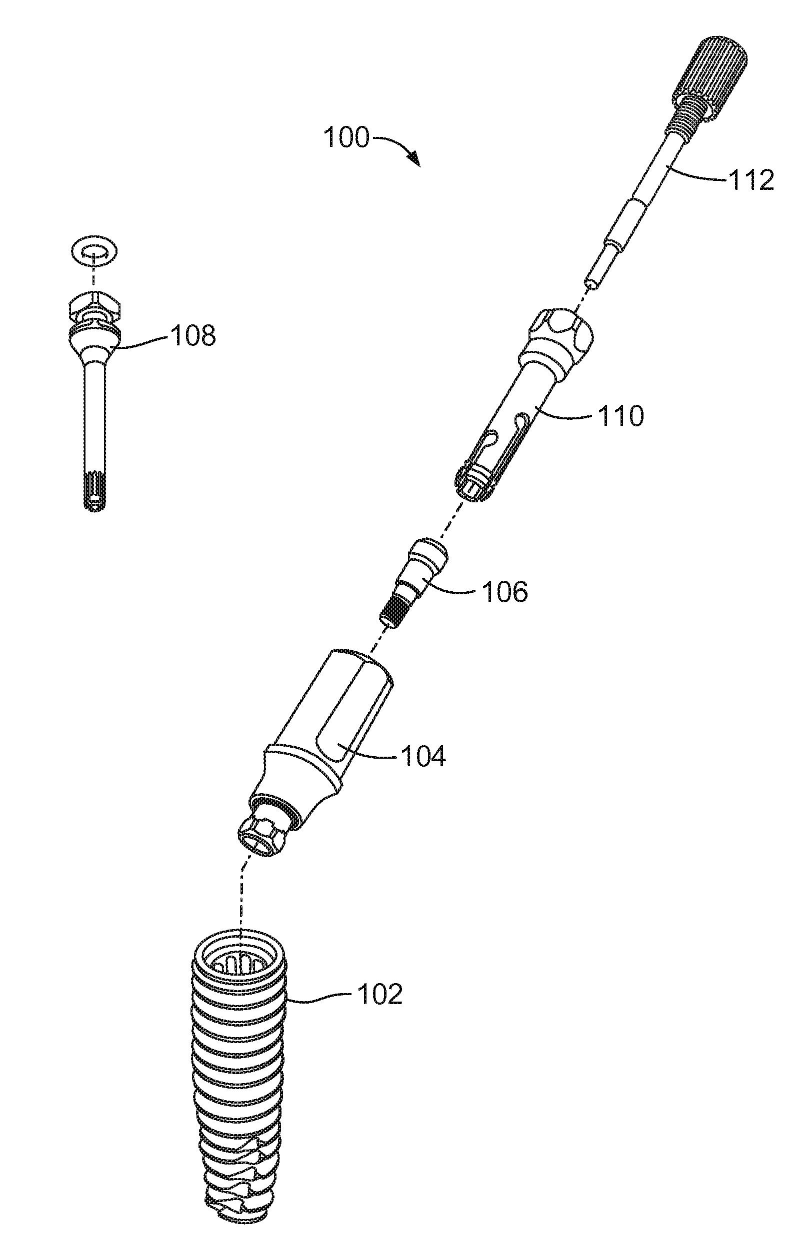
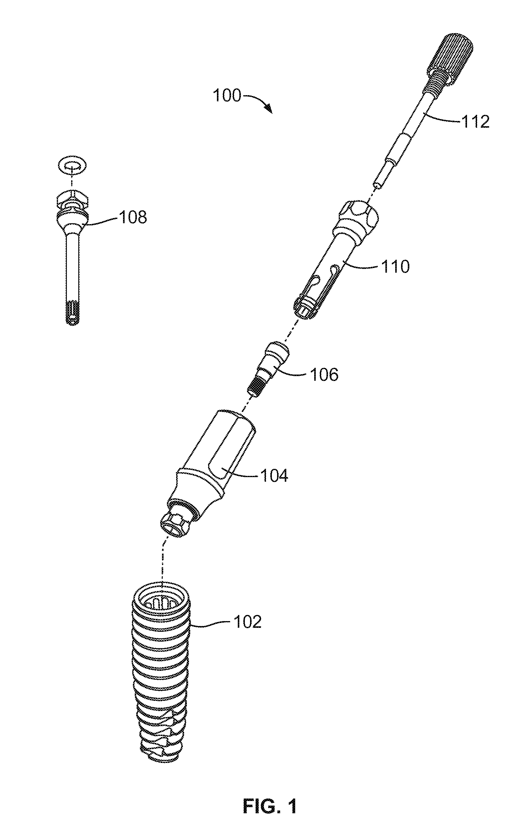
[0054]FIG. 1 is an exploded perspective view of the implant and abutment installation system 100 including an implant 102, an abutment 104, an abutment screw 106, and an implant driver tool 108. FIG. 1 also shows a removal system for the abutment 104 including an abutment removal insert tool 110, and an abutment removal tool screw 112. The components shown in FIG. 1 are used in dental restorative processes. As is known, the implant 102 is implanted into the bone of a patient's jaw. The implant driver tool 108 is used to fix the implant 102 into the bone. The abutment 104 may be a standard part or customized to replace the patient's tooth and is attached to the implant 102. The abutment 104 is fixed to the implant 102 via the abutment screw 106, which may be installed via a screw driver tool. In cases where the abutment 104 must be removed from the implant 102 and cannot be readily removed by hand (after the abutment screw 106 is removed), the abutment removal insert tool 110 is used...


PUM


Abstract

A dental assembly for vertical attachment of an implant to a dental abutment for restorative dental procedures is disclosed. The implant includes a cylindrical body having an interior bore formed between a distal end and a proximal end. An abutment interface is formed on the proximal end of the cylindrical body. The interface includes a radial annular interior surface and a flat annular stop surface circumferentially bordering the interior bore. The assembly also includes an abutment including a stem and a post coupled to the stem. An interior bore is formed through the stem and the post. The abutment includes an interface section between the post and the stem. The interface section may include an annular radially curved exterior surface proximate to the post. The radially curved exterior surface and the circular flat surface interfaces with the abutment interface of the dental implant.

Description

PRIORITY CLAIM AND CROSS REFERENCE TO RELATED APPLICATIONS[0001]This application claims priority to U.S. Provisional Application No. 61 / 502,091, filed on Jun. 28, 2011 which is incorporated herein its entirety.TECHNICAL FIELD[0002]This disclosure relates to restorative dental implants and abutments and related tools for the assembly and disassembly of the same.BACKGROUND[0003]Single tooth restorations present the unique requirement that they must be supported non-rotationally on an underlying abutment. When a prepared natural tooth is the underlying abutment, this requirement is met in the normal course of preparing the abutment with a non-circular cross-section. Likewise, when the underlying abutment is a post fitted onto an implant, this requirement is met by preparing the post with a noncircular cross-section. This latter scenario can be more complicated due to the added connection between the implant and the abutment.[0004]Typically, a dental implant is implanted into the bone o...

Claims


Application Information

Patent Timeline
Patent Type & Authority Applications(United States)
IPC IPC(8): A61C8/00
CPCA61C8/0018A61C8/0022A61C8/0059A61C8/0057A61C8/0066A61C8/0068A61C8/0089A61C8/006
Inventor BELLANCA, JOHN J.ROGERS, DAN P.HERRINGTON, STEPHEN M.TOWSE, ROSS W.GOODMAN, RALPH E.SUTTIN, ZACHARY B.SCALISE, ISABELBOBBY, MICHAEL
Owner BIOMET 3I LLC
Why Eureka
Try Eureka